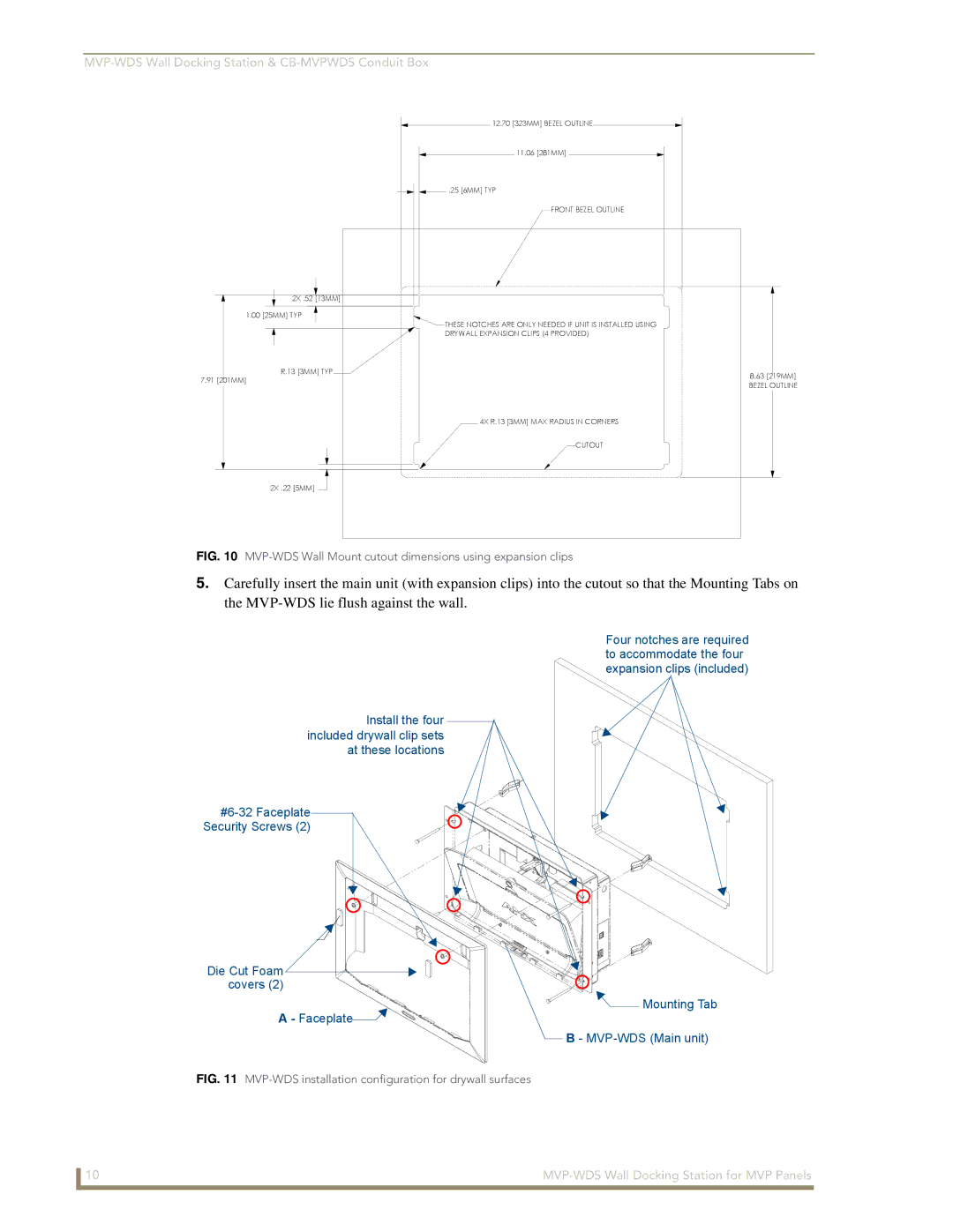
12.70 [323MM] BEZEL OUTLINE
11.06 [281MM]
.25 [6MM] TYP
FRONT BEZEL OUTLINE
2X .52 [13MM]
1.00 [25MM] TYP
![]() THESE NOTCHES ARE ONLY NEEDED IF UNIT IS INSTALLED USING DRYWALL EXPANSION CLIPS (4 PROVIDED)
THESE NOTCHES ARE ONLY NEEDED IF UNIT IS INSTALLED USING DRYWALL EXPANSION CLIPS (4 PROVIDED)
R.13 [3MM] TYP
7.91 [201MM]
4X R.13 [3MM] MAX RADIUS IN CORNERS
CUTOUT
2X .22 [5MM] ![]()
8.63[219MM]
BEZEL OUTLINE
FIG. 10 MVP-WDS Wall Mount cutout dimensions using expansion clips
5.Carefully insert the main unit (with expansion clips) into the cutout so that the Mounting Tabs on the
Four notches are required to accommodate the four expansion clips (included)
Install the four included drywall clip sets at these locations
Security Screws (2)
Die Cut Foam covers (2)
A - Faceplate![]()
![]()
![]() Mounting Tab
Mounting Tab
B -
FIG. 11 MVP-WDS installation configuration for drywall surfaces
10 |