Although there are wiring knockouts are on both sides of the conduit box, the knockouts on the right side will be used for the
2.Using either nails or screws, fasten the conduit box to the stud through the five Stud Fastening Holes.
3.Remove the wiring knockouts from the right side of the conduit box to accommodate cabling to the
4.Thread the USB and Power cables through the knockouts on the right of the conduit box. It is recommended that you test these connections before fully installing the WDS.
5.Install the drywall/sheetrock before inserting the
Removing the MVP-WDS Faceplate
The faceplate must be removed from the main
1.Place the
2.Connect the
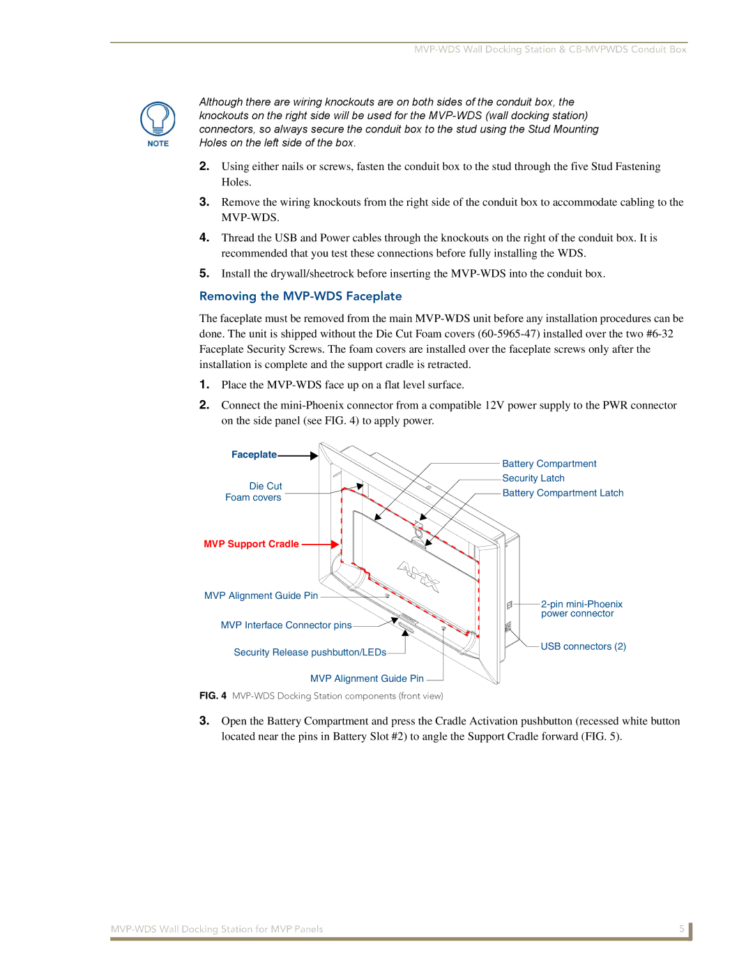
Faceplate![]()
Die Cut
Foam covers
MVP Support Cradle 

MVP Alignment Guide Pin 
![]()
![]()
![]()
MVP Interface Connector pins ![]()
Security Release pushbutton/LEDs![]()
MVP Alignment Guide Pin
FIG. 4 MVP-WDS Docking Station components (front view)
Battery Compartment
Security Latch
Battery Compartment Latch
![]() USB connectors (2)
USB connectors (2)
3.Open the Battery Compartment and press the Cradle Activation pushbutton (recessed white button located near the pins in Battery Slot #2) to angle the Support Cradle forward (FIG. 5).
5 | |
|
|