Replacement drywall clip sets cab be ordered from AMX.
6.Tighten all four drywall clip sets (screws and clips) until both Mounting Tabs are securely fastened and flush against the wall.
7.Follow the steps outlined in the Replacing the Faceplate on the
Installing the
Use
Refer to
It is recommended that you cutout the surface slightly smaller than what is outlined in the installation drawings so that you can make any necessary cutout adjustments.
The outer frame Mounting Tabs must be installed so thatthey are flush against the mounting surface.
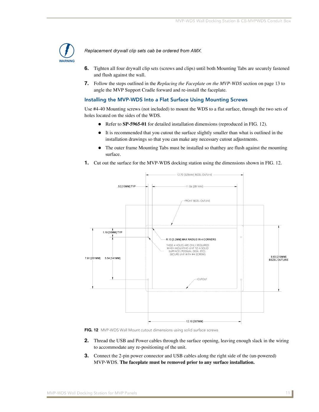
1.Cut out the surface for the
|
| 12.70 [323MM] BEZEL OUTLINE |
.52 [13MM] TYP | 11.06 [281MM] | |
|
| FRONT BEZEL OUTLINE |
|
|
|
| 1.19 [30MM] TYP |
| |
|
| R.13 [3.2MM] MAX RADIUS IN 4 CORNERS | |
|
| THESE 4 HOLES ARE ONLY REQUIRED | |
|
| WHEN MOUNTING UNIT TO A SOLID | |
|
| SURFACE (PODIUM, DESK, ETC). | |
|
| SECURE UNIT WITH #4 SCREWS | |
7.91 [201MM] | 5.54 [141MM] | 8.63 [219MM] | |
BEZEL OUTLINE | |||
|
|
CUTOUT
12.10 [307MM]
FIG. 12 MVP-WDS Wall Mount cutout dimensions using solid surface screws
2.Thread the USB and Power cables through the surface opening, leaving enough slack in the wiring to accommodate any
3.Connect the
11 | |
|
|