MVP-WDS Specifications (Cont.)
Other AMX Equipment:
•
•
-One Silver Cradle Bezel/Faceplate
-One Silver Cradle Pivot
-One Silver Battery Cover
-One securing rare earth magnet
-One securing magnet cup
-One
-Two plastic Die Cut Foam covers
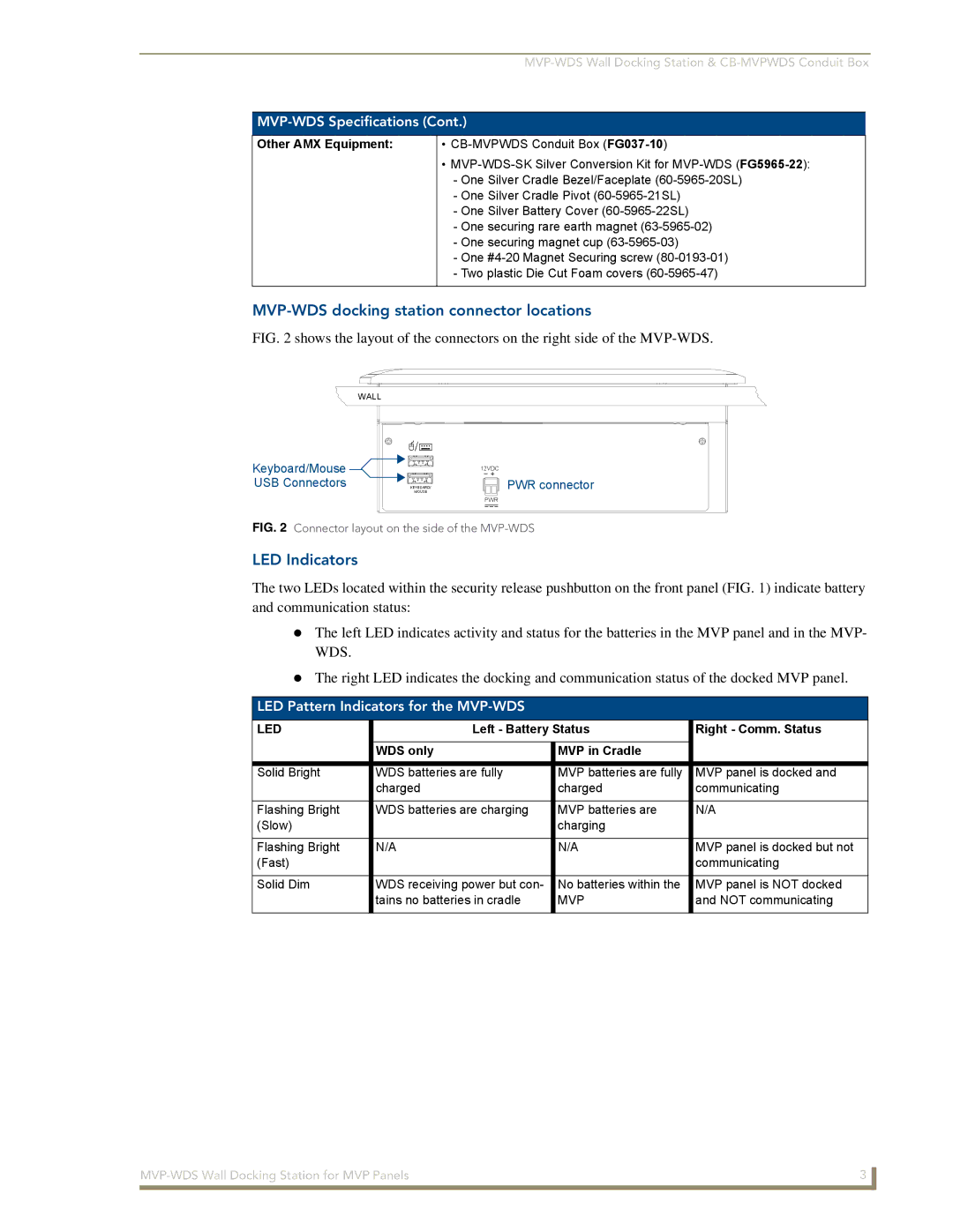
MVP-WDS docking station connector locations
FIG. 2 shows the layout of the connectors on the right side of the MVP-WDS.
WALL
Keyboard/Mouse ![]() USB Connectors
USB Connectors ![]()
![]()
| 12VDC |
MOUSE | PWR connector |
KEYBOARD/ |
|
PWR
FIG. 2 Connector layout on the side of the MVP-WDS
LED Indicators
The two LEDs located within the security release pushbutton on the front panel (FIG. 1) indicate battery and communication status:
The left LED indicates activity and status for the batteries in the MVP panel and in the MVP- WDS.
The right LED indicates the docking and communication status of the docked MVP panel.
LED Pattern Indicators for the MVP-WDS
LED | Left - Battery Status | Right - Comm. Status | |
|
|
|
|
| WDS only | MVP in Cradle |
|
|
|
|
|
Solid Bright | WDS batteries are fully | MVP batteries are fully | MVP panel is docked and |
| charged | charged | communicating |
|
|
|
|
Flashing Bright | WDS batteries are charging | MVP batteries are | N/A |
(Slow) |
| charging |
|
|
|
|
|
Flashing Bright | N/A | N/A | MVP panel is docked but not |
(Fast) |
|
| communicating |
|
|
|
|
Solid Dim | WDS receiving power but con- | No batteries within the | MVP panel is NOT docked |
| tains no batteries in cradle | MVP | and NOT communicating |
|
|
|
|
3 | |
|
|