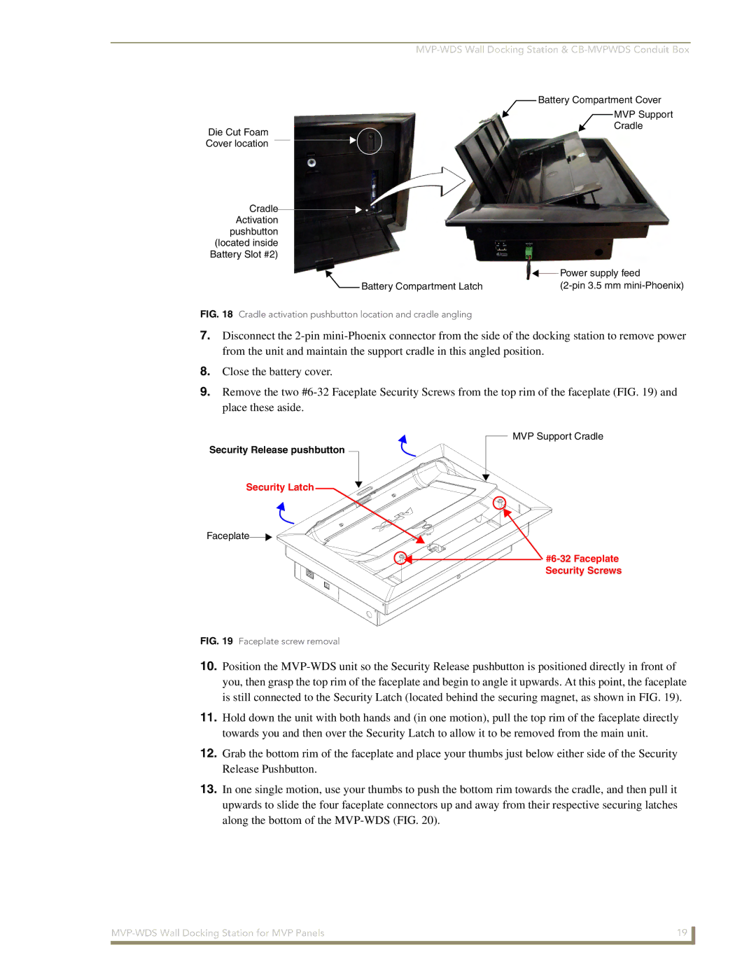
Battery Compartment Cover
Die Cut Foam Cover location
MVP Support Cradle
Cradle Activation
pushbutton (located inside Battery Slot #2)
|
| Power supply feed |
|
| |
Battery Compartment Latch |
|
FIG. 18 Cradle activation pushbutton location and cradle angling
7.Disconnect the
8.Close the battery cover.
9.Remove the two
Security Release pushbutton
Security Latch
Faceplate![]()
![]()
FIG. 19 Faceplate screw removal
MVP Support Cradle
10.Position the
11.Hold down the unit with both hands and (in one motion), pull the top rim of the faceplate directly towards you and then over the Security Latch to allow it to be removed from the main unit.
12.Grab the bottom rim of the faceplate and place your thumbs just below either side of the Security Release Pushbutton.
13.In one single motion, use your thumbs to push the bottom rim towards the cradle, and then pull it upwards to slide the four faceplate connectors up and away from their respective securing latches along the bottom of the
19 | |
|
|