Verify that the terminal end of the power cable is not connected to a power source before plugging in the
The USB connectors can be from either a USB extension cable, or a wireless USB RF transmitter.
Don’t disconnect the PWR and USB connectors from the
4.Test the Power and USB connections before fully installing the WDS. Refer to the LED Indicators table on page 3 for blink pattern information.
Applying power to the
5.Disconnect the terminal end of the power cable from the connected power supply.
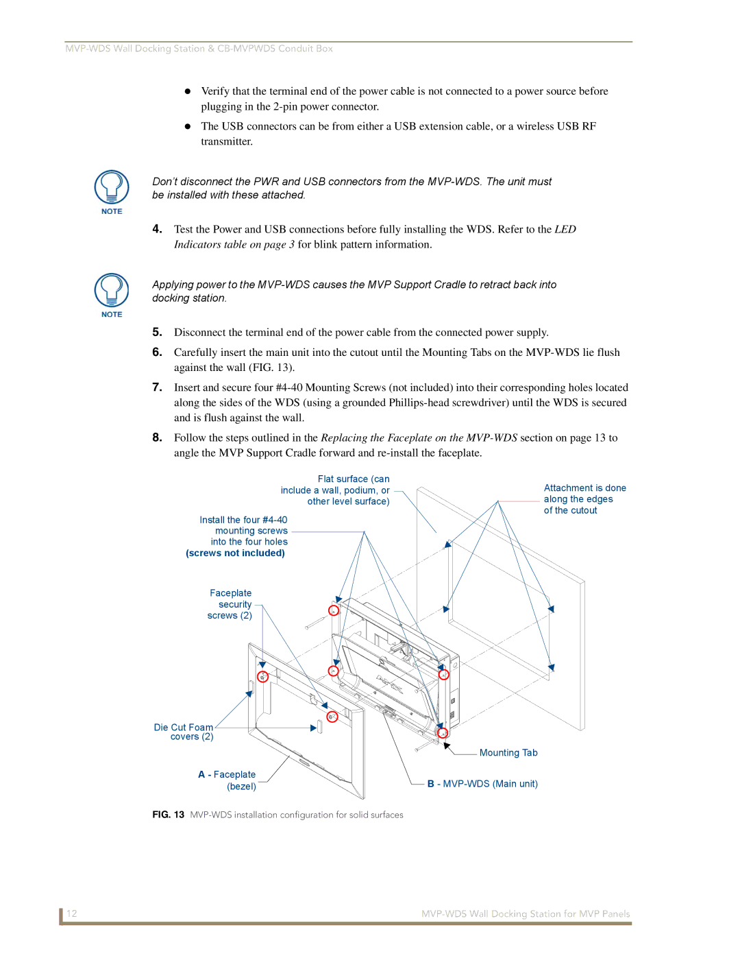
6.Carefully insert the main unit into the cutout until the Mounting Tabs on the
7.Insert and secure four
8.Follow the steps outlined in the Replacing the Faceplate on the
Flat surface (can include a wall, podium, or other level surface)
Install the four
(screws not included)
Faceplate security screws (2)
Die Cut Foam covers (2)
A - Faceplate (bezel)
Attachment is done along the edges of the cutout
![]() Mounting Tab
Mounting Tab
B-
FIG. 13 MVP-WDS installation configuration for solid surfaces
12 |