Installation
)
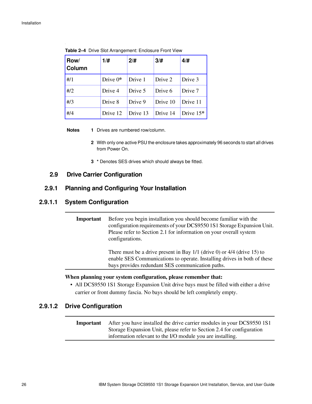
Table
Row/ |
| 1/# | 2/# | 3/# | 4/# |
Column |
|
|
|
|
|
|
|
|
|
|
|
#/1 |
| Drive 0* | Drive 1 | Drive 2 | Drive 3 |
|
|
|
|
|
|
#/2 |
| Drive 4 | Drive 5 | Drive 6 | Drive 7 |
|
|
|
|
|
|
#/3 |
| Drive 8 | Drive 9 | Drive 10 | Drive 11 |
|
|
|
|
|
|
#/4 |
| Drive 12 | Drive 13 | Drive 14 | Drive 15* |
|
|
|
|
|
|
Notes | 1 Drives are numbered row/column. |
| |||
2With only one active PSU the enclosure takes approximately 96 seconds to start all drives from Power On.
3* Denotes SES drives which should always be fitted.
2.9Drive Carrier Configuration
2.9.1Planning and Configuring Your Installation
2.9.1.1System Configuration
Important Before you begin installation you should become familiar with the configuration requirements of your DCS9550 1S1 Storage Expansion Unit. Please refer to Section 2.1 for information on your overall system configurations.
There must be a drive present in Bay 1/1 (drive 0) or 4/4 (drive 15) to enable SES Communications to operate. Installing drives in both of these bays provides redundant SES communication paths.
When planning your system configuration, please remember that:
•All DCS9550 1S1 Storage Expansion Unit drive bays must be filled with either a drive carrier or front dummy fascia. No bays should be left completely empty.
2.9.1.2Drive Configuration
Important After you have installed the drive carrier modules in your DCS9550 1S1 Storage Expansion Unit, please refer to Section 2.4 for configuration information relevant to the I/O module you are installing.
26 | IBM System Storage DCS9550 1S1 Storage Expansion Unit Installation, Service, and User Guide |