Installation
).
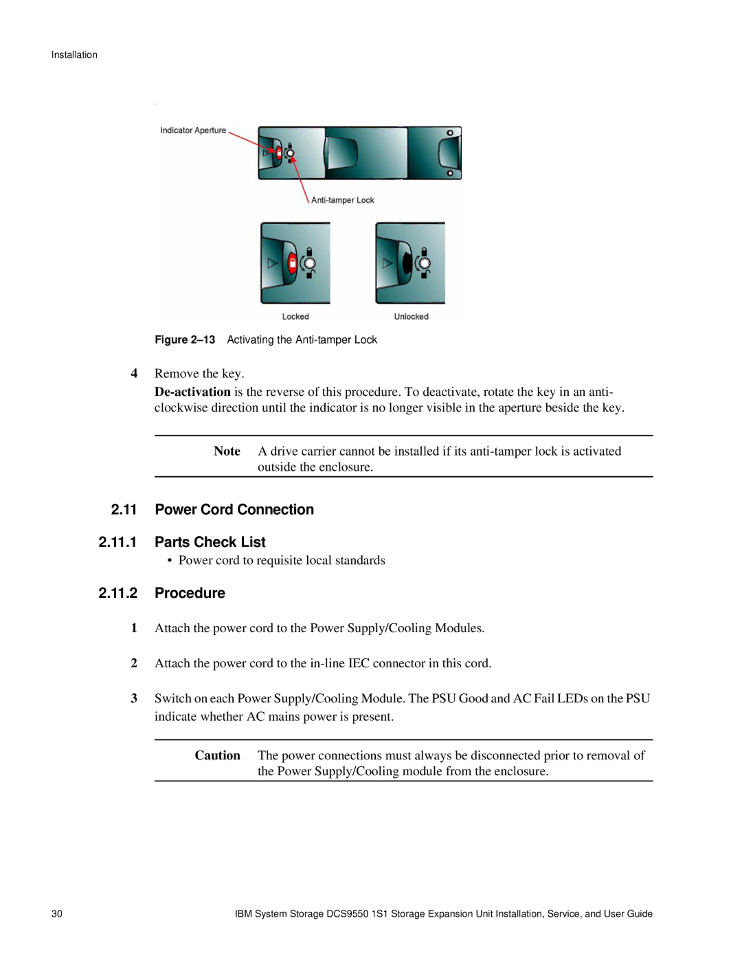
Figure 2–13 Activating the Anti-tamper Lock
4Remove the key.
Note A drive carrier cannot be installed if its
2.11Power Cord Connection
2.11.1Parts Check List
•Power cord to requisite local standards
2.11.2Procedure
1Attach the power cord to the Power Supply/Cooling Modules.
2Attach the power cord to the
3Switch on each Power Supply/Cooling Module. The PSU Good and AC Fail LEDs on the PSU indicate whether AC mains power is present.
Caution The power connections must always be disconnected prior to removal of the Power Supply/Cooling module from the enclosure.
30 | IBM System Storage DCS9550 1S1 Storage Expansion Unit Installation, Service, and User Guide |