Introduction
1.2.4Drive Carrier Module
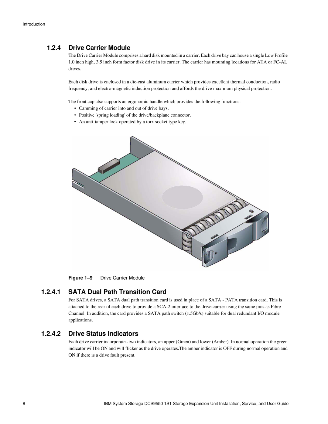
The Drive Carrier Module comprises a hard disk mounted in a carrier. Each drive bay can house a single Low Profile
1.0inch high, 3.5 inch form factor disk drive in its carrier. The carrier has mounting locations for ATA or
Each disk drive is enclosed in a
The front cap also supports an ergonomic handle which provides the following functions:
•Camming of carrier into and out of drive bays.
•Positive 'spring loading' of the drive/backplane connector.
•An
Figure 1–9 Drive Carrier Module
1.2.4.1SATA Dual Path Transition Card
For SATA drives, a SATA dual path transition card is used in place of a SATA - PATA transition card. This is attached to the rear of each drive to provide a
1.2.4.2Drive Status Indicators
Each drive carrier incorporates two indicators, an upper (Green) and lower (Amber). In normal operation the green indicator will be ON and will flicker as the drive operates.The amber indicator is OFF during normal operation and ON if there is a drive fault present.
8 | IBM System Storage DCS9550 1S1 Storage Expansion Unit Installation, Service, and User Guide |