Chapter 2 | Product Overview |
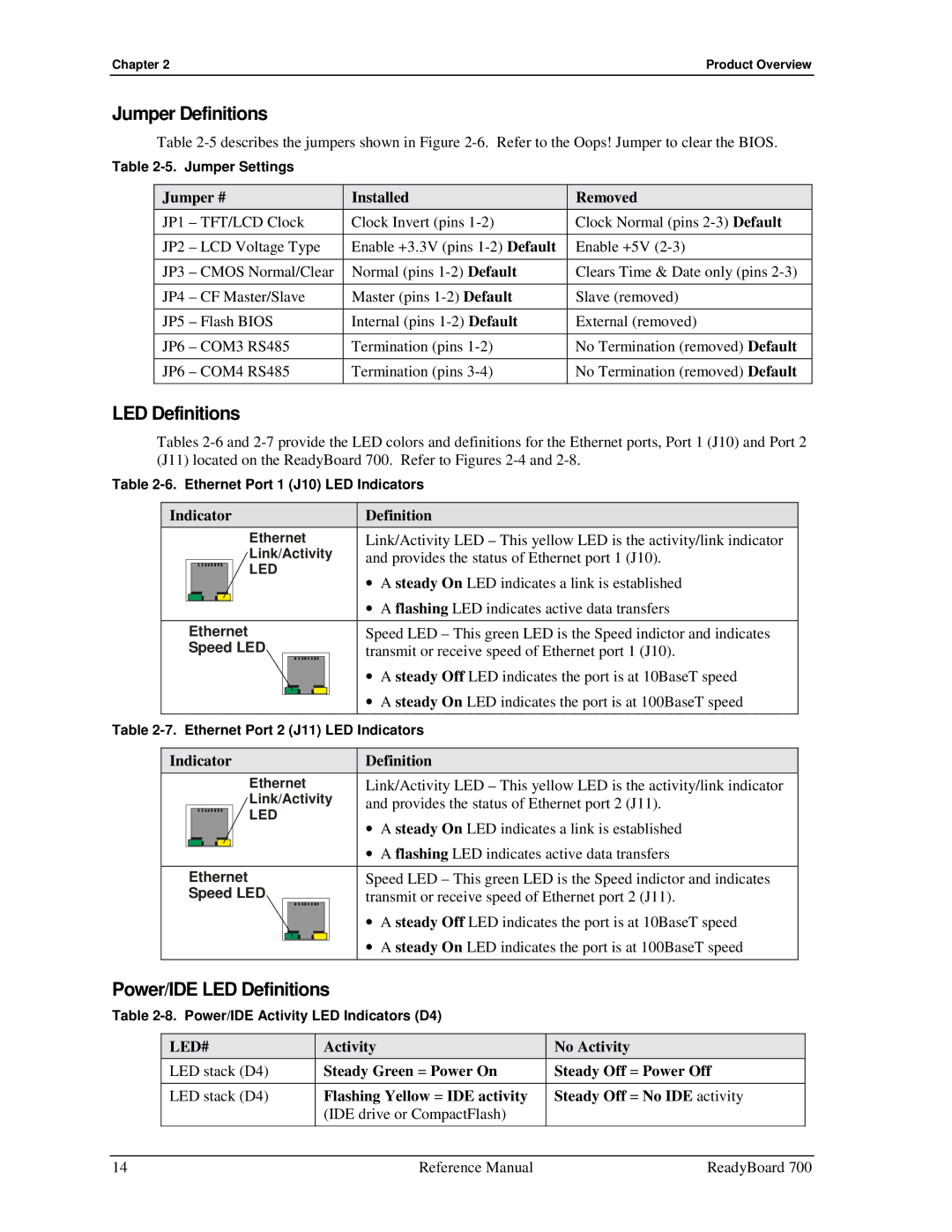
Jumper Definitions
Table
Table
Jumper # | Installed | Removed |
JP1 – TFT/LCD Clock | Clock Invert (pins | Clock Normal (pins |
JP2 – LCD Voltage Type | Enable +3.3V (pins | Enable +5V |
|
|
|
JP3 – CMOS Normal/Clear | Normal (pins | Clears Time & Date only (pins |
|
|
|
JP4 – CF Master/Slave | Master (pins | Slave (removed) |
JP5 – Flash BIOS | Internal (pins | External (removed) |
|
|
|
JP6 – COM3 RS485 | Termination (pins | No Termination (removed) Default |
|
|
|
JP6 – COM4 RS485 | Termination (pins | No Termination (removed) Default |
LED Definitions
Tables
Table
Indicator | Definition | ||||||||||
|
|
|
|
| Ethernet | Link/Activity LED – This yellow LED is the activity/link indicator | |||||
|
|
|
|
| Link/Activity | and provides the status of Ethernet port 1 (J10). | |||||
|
|
|
|
| LED | • A steady On LED indicates a link is established | |||||
|
|
|
|
|
|
|
|
|
|
| |
|
|
|
|
|
|
|
|
|
|
| • A flashing LED indicates active data transfers |
|
|
|
|
|
|
|
|
|
|
| |
|
|
| |||||||||
| Ethernet | Speed LED – This green LED is the Speed indictor and indicates | |||||||||
| Speed LED |
|
| transmit or receive speed of Ethernet port 1 (J10). | |||||||
|
|
|
|
|
|
|
|
|
|
| • A steady Off LED indicates the port is at 10BaseT speed |
|
|
|
|
|
|
|
|
|
|
| • A steady On LED indicates the port is at 100BaseT speed |
|
|
|
|
|
|
|
|
|
|
| |
|
|
|
|
|
|
|
|
|
|
|
|
Table
Indicator | Definition | |||||||||||
|
|
|
|
|
| Ethernet | Link/Activity LED – This yellow LED is the activity/link indicator | |||||
|
|
|
|
|
| Link/Activity | and provides the status of Ethernet port 2 (J11). | |||||
|
|
|
|
|
| LED | • A steady On LED indicates a link is established | |||||
|
|
|
|
|
|
|
|
|
|
|
| |
|
|
|
|
|
|
|
|
|
|
|
| • A flashing LED indicates active data transfers |
|
|
|
|
|
|
|
|
|
|
|
| |
|
|
| ||||||||||
| Ethernet | Speed LED – This green LED is the Speed indictor and indicates | ||||||||||
| Speed LED |
|
| transmit or receive speed of Ethernet port 2 (J11). | ||||||||
|
|
|
|
|
|
|
|
|
|
|
| • A steady Off LED indicates the port is at 10BaseT speed |
|
|
|
|
|
|
|
|
|
|
|
| • A steady On LED indicates the port is at 100BaseT speed |
|
|
|
|
|
|
|
|
|
|
|
| |
|
|
|
|
|
|
|
|
|
|
|
|
|
Power/IDE LED Definitions
Table
LED# | Activity | No Activity |
LED stack (D4) | Steady Green = Power On | Steady Off = Power Off |
|
|
|
LED stack (D4) | Flashing Yellow = IDE activity | Steady Off = No IDE activity |
| (IDE drive or CompactFlash) |
|
14 | Reference Manual | ReadyBoard 700 |