Chapter 3 | Hardware |
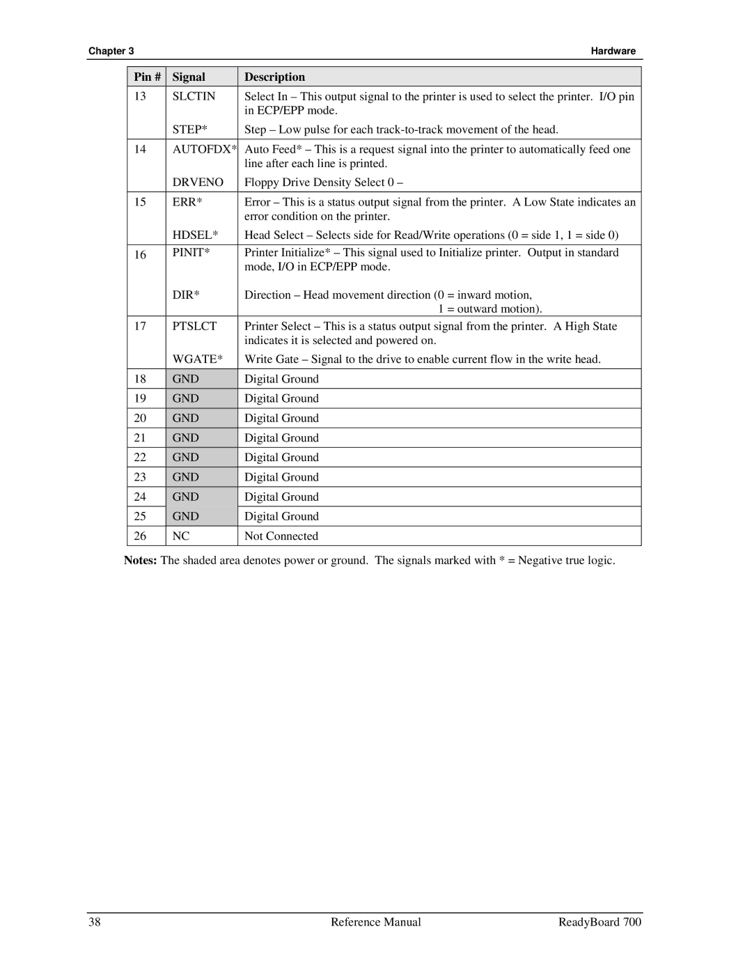
Pin # | Signal | Description |
13 | SLCTIN | Select In – This output signal to the printer is used to select the printer. I/O pin |
|
| in ECP/EPP mode. |
| STEP* | Step – Low pulse for each |
|
|
|
14 | AUTOFDX* | Auto Feed* – This is a request signal into the printer to automatically feed one |
|
| line after each line is printed. |
| DRVENO | Floppy Drive Density Select 0 – |
|
|
|
15 | ERR* | Error – This is a status output signal from the printer. A Low State indicates an |
|
| error condition on the printer. |
| HDSEL* | Head Select – Selects side for Read/Write operations (0 = side 1, 1 = side 0) |
|
|
|
16 | PINIT* | Printer Initialize* – This signal used to Initialize printer. Output in standard |
|
| mode, I/O in ECP/EPP mode. |
| DIR* | Direction – Head movement direction (0 = inward motion, |
|
| 1 = outward motion). |
17 | PTSLCT | Printer Select – This is a status output signal from the printer. A High State |
|
| indicates it is selected and powered on. |
| WGATE* | Write Gate – Signal to the drive to enable current flow in the write head. |
|
|
|
18 | GND | Digital Ground |
19 | GND | Digital Ground |
20 | GND | Digital Ground |
21 | GND | Digital Ground |
22 | GND | Digital Ground |
23 | GND | Digital Ground |
24 | GND | Digital Ground |
|
|
|
25 | GND | Digital Ground |
26 | NC | Not Connected |
|
|
|
Notes: The shaded area denotes power or ground. The signals marked with * = Negative true logic.
38 | Reference Manual | ReadyBoard 700 |