Chapter 3 | Hardware |
Floppy/Parallel Interface (J20)
The Southbridge (VT82C686B) chip provides the floppy controller and the parallel port controller. The floppy controller and the parallel port controller share the same output connector (J20) on the board and the device selection is made in the BIOS Setup Utility. Refer to Table
•Floppy Port Controller supports two floppy drives
•Parallel Port controller supports standard parallel,
NOTE | Due to the multiplexed nature of the signals for the floppy and parallel ports, |
| you can only connect one of these devices at a time. Refer to Chapter 4, BIOS |
| Setup later in this manual when selecting the floppy or parallel device in the |
| BIOS Setup Utility. A reboot is necessary for a change in the BIOS settings to |
| take affect. |
|
|
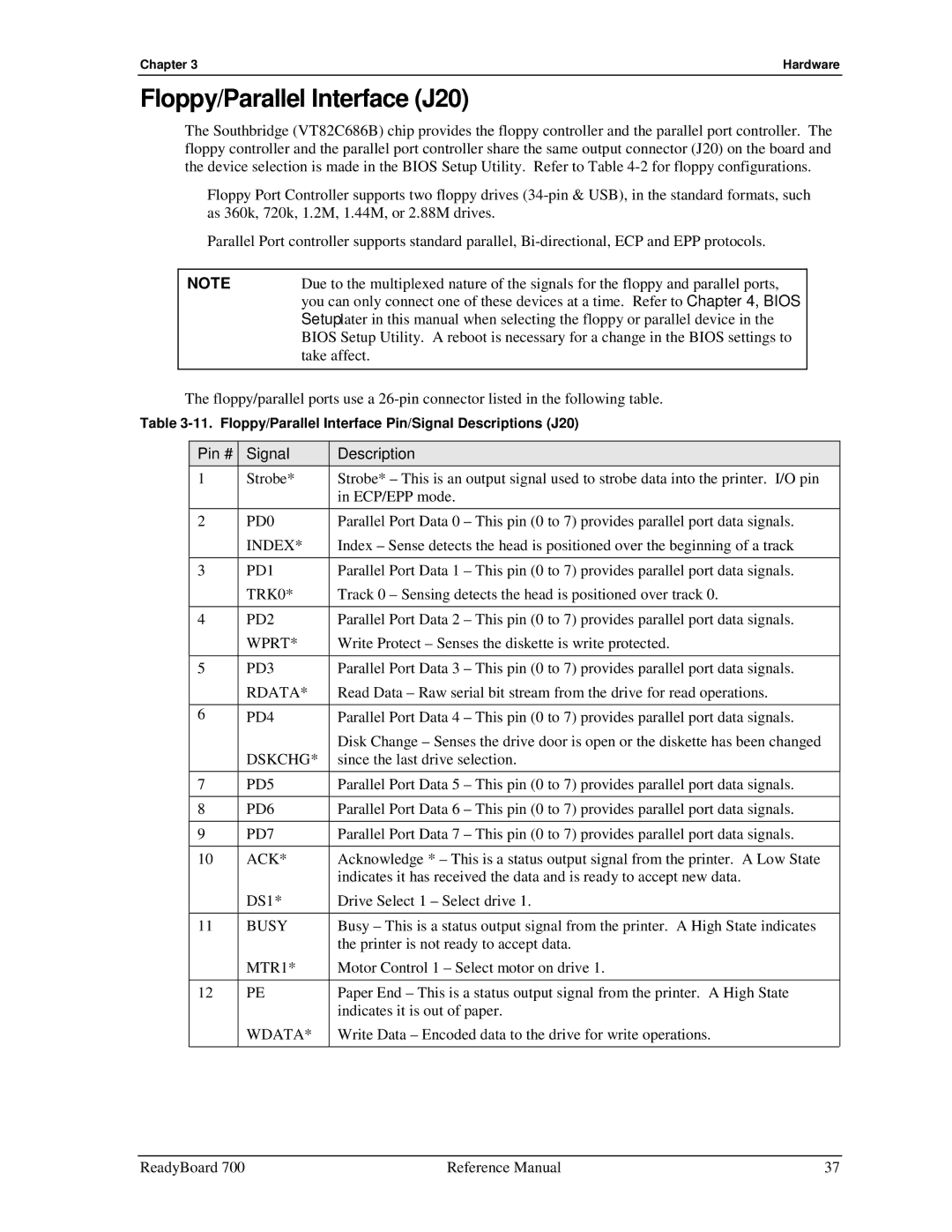
The floppy/parallel ports use a
Table
Pin # | Signal | Description |
1 | Strobe* | Strobe* – This is an output signal used to strobe data into the printer. I/O pin |
|
| in ECP/EPP mode. |
2 | PD0 | Parallel Port Data 0 – This pin (0 to 7) provides parallel port data signals. |
| INDEX* | Index – Sense detects the head is positioned over the beginning of a track |
|
|
|
3 | PD1 | Parallel Port Data 1 – This pin (0 to 7) provides parallel port data signals. |
| TRK0* | Track 0 – Sensing detects the head is positioned over track 0. |
|
|
|
4 | PD2 | Parallel Port Data 2 – This pin (0 to 7) provides parallel port data signals. |
| WPRT* | Write Protect – Senses the diskette is write protected. |
|
|
|
5 | PD3 | Parallel Port Data 3 – This pin (0 to 7) provides parallel port data signals. |
| RDATA* | Read Data – Raw serial bit stream from the drive for read operations. |
|
|
|
6 | PD4 | Parallel Port Data 4 – This pin (0 to 7) provides parallel port data signals. |
| DSKCHG* | Disk Change – Senses the drive door is open or the diskette has been changed |
| since the last drive selection. | |
7 | PD5 | Parallel Port Data 5 – This pin (0 to 7) provides parallel port data signals. |
|
|
|
8 | PD6 | Parallel Port Data 6 – This pin (0 to 7) provides parallel port data signals. |
|
|
|
9 | PD7 | Parallel Port Data 7 – This pin (0 to 7) provides parallel port data signals. |
|
|
|
10 | ACK* | Acknowledge * – This is a status output signal from the printer. A Low State |
|
| indicates it has received the data and is ready to accept new data. |
| DS1* | Drive Select 1 – Select drive 1. |
|
|
|
11 | BUSY | Busy – This is a status output signal from the printer. A High State indicates |
|
| the printer is not ready to accept data. |
| MTR1* | Motor Control 1 – Select motor on drive 1. |
|
|
|
12 | PE | Paper End – This is a status output signal from the printer. A High State |
|
| indicates it is out of paper. |
| WDATA* | Write Data – Encoded data to the drive for write operations. |
ReadyBoard 700 | Reference Manual | 37 |
