Chapter 2 | Product Overview |
Q10
Q9
Q8 U24
U23
L1
U29 | U28 | |
|
|
|
| D12 |
|
|
|
|
D11
|
|
|
| U27 | |
|
| U26 |
|
|
|
|
|
|
|
| |
|
|
|
|
| |
|
|
|
|
| |
|
|
|
|
| |
|
|
|
|
| |
|
|
|
|
|
|
|
|
|
|
|
|
|
| U25 |
|
|
|
|
|
|
|
| |
|
|
|
|
| |
|
|
|
|
|
|
| D10 |
| Q6 | ||
|
|
|
|
|
|
|
|
|
|
|
|
|
|
| Q5 | ||
RB700_02aa
Q7
D9
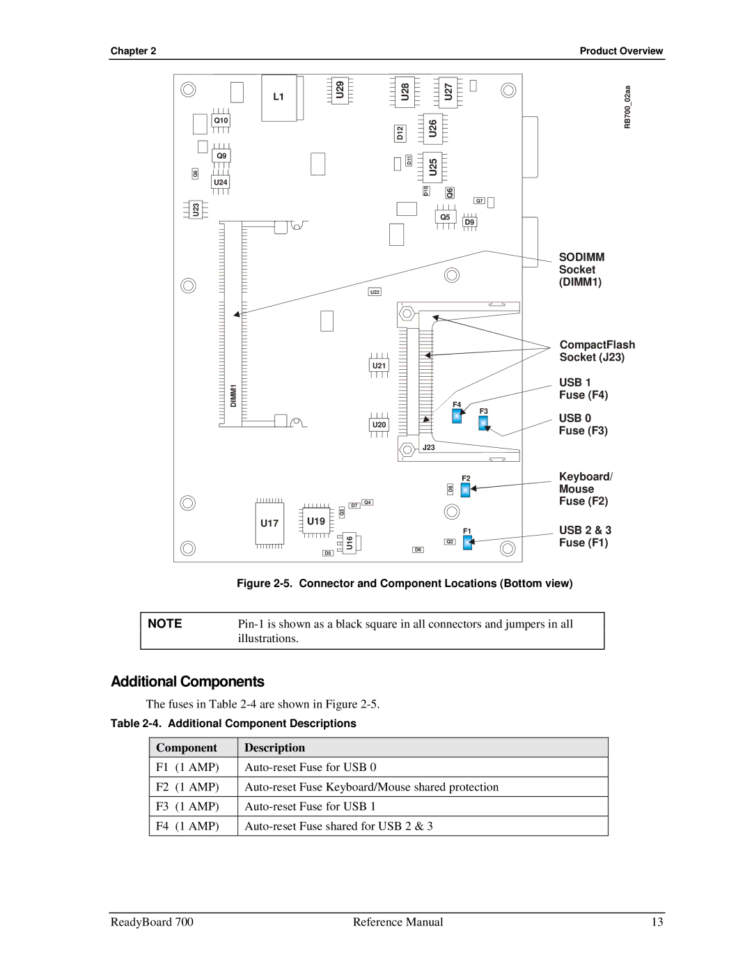
SODIMM Socket (DIMM1)
U22
U21
DIMM1
U20
D7 ![]()
![]() Q4
Q4
Q3
U17 U19
U16
D5
|
| CompactFlash |
|
| Socket (J23) |
|
| USB 1 |
F4 |
| Fuse (F4) |
F3 |
| |
| USB 0 | |
|
| |
|
| Fuse (F3) |
J23 |
|
|
F2 |
| Keyboard/ |
D8 |
| Mouse |
|
| Fuse (F2) |
F1 |
| USB 2 & 3 |
Q2 |
| Fuse (F1) |
|
| |
D6 |
|
|
| Figure |
|
|
NOTE | |
| illustrations. |
|
|
Additional Components
The fuses in Table
Table
Component | Description | |
F1 | (1 AMP) | |
|
|
|
F2 | (1 AMP) | |
|
|
|
F3 | (1 AMP) | |
|
|
|
F4 | (1 AMP) | |
|
|
|
ReadyBoard 700 | Reference Manual | 13 |