Chapter 3 |
|
| Hardware | ||
|
|
|
|
|
|
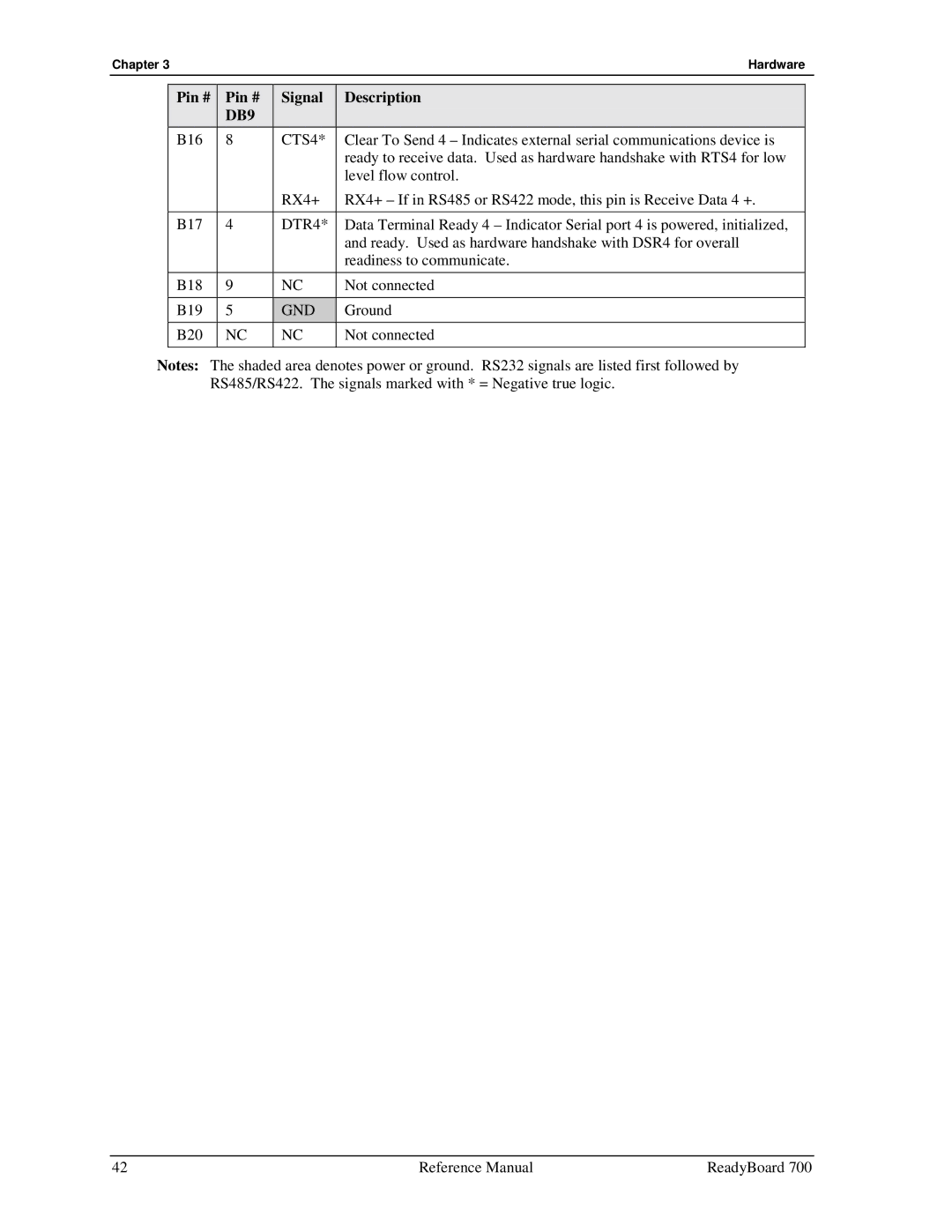
| Pin # | Pin # | Signal | Description |
|
|
| DB9 |
|
|
|
| B16 | 8 | CTS4* | Clear To Send 4 – Indicates external serial communications device is |
|
|
|
|
| ready to receive data. Used as hardware handshake with RTS4 for low |
|
|
|
|
| level flow control. |
|
|
|
| RX4+ | RX4+ – If in RS485 or RS422 mode, this pin is Receive Data 4 +. |
|
|
|
|
|
|
|
| B17 | 4 | DTR4* | Data Terminal Ready 4 – Indicator Serial port 4 is powered, initialized, |
|
|
|
|
| and ready. Used as hardware handshake with DSR4 for overall |
|
|
|
|
| readiness to communicate. |
|
| B18 | 9 | NC | Not connected |
|
|
|
|
|
|
|
| B19 | 5 | GND | Ground |
|
| B20 | NC | NC | Not connected |
|
|
|
|
|
|
|
Notes: The shaded area denotes power or ground. RS232 signals are listed first followed by RS485/RS422. The signals marked with * = Negative true logic.
42 | Reference Manual | ReadyBoard 700 |