Chapter 3 | Hardware |
Interrupt Channel Assignments
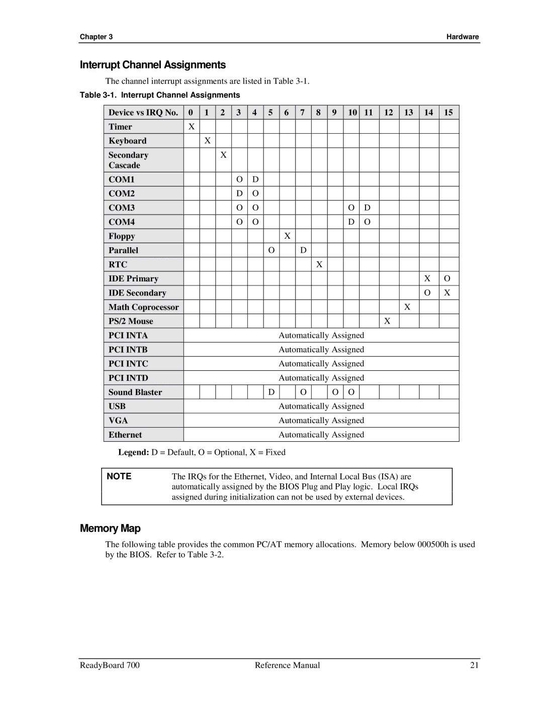
The channel interrupt assignments are listed in Table
Table
| Device vs IRQ No. | 0 | 1 |
| 2 | 3 | 4 | 5 |
| 6 | 7 |
| 8 | 9 | 10 | 11 | 12 | 13 | 14 | 15 | ||
| Timer |
| X |
|
|
|
|
|
|
|
|
|
|
|
|
|
|
|
|
|
| |
| Keyboard |
|
| X |
|
|
|
|
|
|
|
|
|
|
|
|
|
|
|
|
| |
| Secondary |
|
|
|
| X |
|
|
|
|
|
|
|
|
|
|
|
|
|
|
|
|
| Cascade |
|
|
|
|
|
|
|
|
|
|
|
|
|
|
|
|
|
|
|
|
|
| COM1 |
|
|
|
|
| O | D |
|
|
|
|
|
|
|
|
|
|
|
|
|
|
| COM2 |
|
|
|
|
| D | O |
|
|
|
|
|
|
|
|
|
|
|
|
|
|
| COM3 |
|
|
|
|
| O | O |
|
|
|
|
|
|
| O | D |
|
|
|
|
|
| COM4 |
|
|
|
|
| O | O |
|
|
|
|
|
|
| D | O |
|
|
|
|
|
| Floppy |
|
|
|
|
|
|
|
|
| X |
|
|
|
|
|
|
|
|
|
|
|
| Parallel |
|
|
|
|
|
|
| O |
|
| D |
|
|
|
|
|
|
|
|
|
|
| RTC |
|
|
|
|
|
|
|
|
|
|
|
| X |
|
|
|
|
|
|
|
|
| IDE Primary |
|
|
|
|
|
|
|
|
|
|
|
|
|
|
|
|
|
| X | O | |
| IDE Secondary |
|
|
|
|
|
|
|
|
|
|
|
|
|
|
|
|
|
| O | X | |
| Math Coprocessor |
|
|
|
|
|
|
|
|
|
|
|
|
|
|
|
| X |
|
|
| |
| PS/2 Mouse |
|
|
|
|
|
|
|
|
|
|
|
|
|
|
|
| X |
|
|
|
|
| PCI INTA |
|
|
|
|
|
|
|
| Automatically Assigned |
|
| ||||||||||
| PCI INTB |
|
|
|
|
|
|
|
| Automatically Assigned |
|
| ||||||||||
| PCI INTC |
|
|
|
|
|
|
|
| Automatically Assigned |
|
| ||||||||||
| PCI INTD |
|
|
|
|
|
|
|
| Automatically Assigned |
|
| ||||||||||
| Sound Blaster |
|
|
|
|
|
|
| D |
|
| O |
|
| O | O |
|
|
|
|
|
|
| USB |
|
|
|
|
|
|
|
| Automatically Assigned |
|
| ||||||||||
| VGA |
|
|
|
|
|
|
|
| Automatically Assigned |
|
| ||||||||||
| Ethernet |
|
|
|
|
|
|
|
| Automatically Assigned |
|
| ||||||||||
| Legend: D = Default, O = Optional, X = Fixed |
|
|
|
|
|
|
|
|
|
| |||||||||||
|
|
|
|
| ||||||||||||||||||
| NOTE | The IRQs for the Ethernet, Video, and Internal Local Bus (ISA) are |
|
| ||||||||||||||||||
|
| automatically assigned by the BIOS Plug and Play logic. Local IRQs |
|
| ||||||||||||||||||
|
| assigned during initialization can not be used by external devices. |
|
| ||||||||||||||||||
|
|
|
|
|
|
|
|
|
|
|
|
|
|
|
|
|
|
|
|
|
|
|
Memory Map
The following table provides the common PC/AT memory allocations. Memory below 000500h is used by the BIOS. Refer to Table
ReadyBoard 700 | Reference Manual | 21 |