Chapter 2 |
| Product Overview |
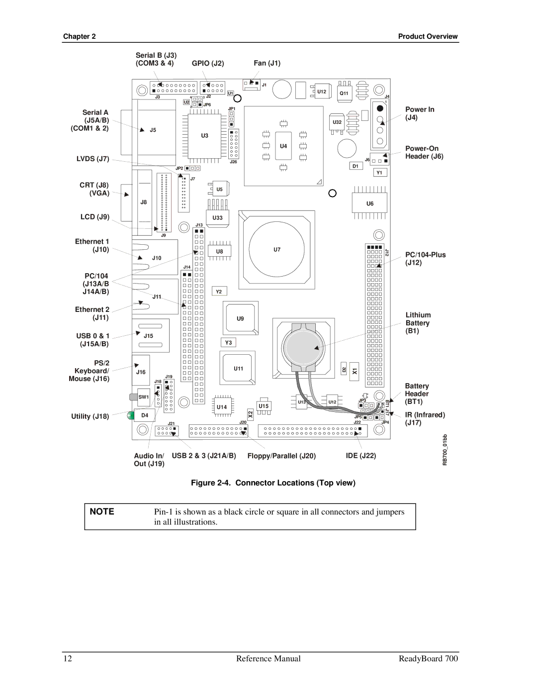
Serial B (J3) | GPIO (J2) | Fan (J1) |
(COM3 & 4) |
J3 | 4 | 3 J2 |
| U2 | JP6 |
J1 |
U1
U12 | Q11 | J4 |
|
| |
|
| 1 |
Serial A | 2 |
|
|
|
|
| |
(J5A/B) |
|
|
|
(COM1 & 2) | J5 | ||
|
| U3 | |
LVDS (J7)
JP2 ![]()
JP1
U4
J26
U32 ![]()
![]()
J6
D1
Y1
Power In (J4)
CRT (J8) (VGA) ![]()
J8
LCD (J9)
J9
Ethernet 1 (J10)
J10
PC/104
(J13A/B
J14A/B)
J11
Ethernet 2 ![]() (J11)
(J11)
USB 0 & 1 ![]() J15 (J15A/B)
J15 (J15A/B)
PS/2 |
|
Keyboard/ | J16 |
Mouse (J16) | J19 |
J18 | |
| SW1 |
Utility (J18) | D4 |
J21
J7
J13
J14
U5
U33
U8U7
Y2
U9 |
Y3 |
U11 |
U14U15
X2
J20
U6
J12 | |
| |
| (J12) |
Lithium Battery (B1)
D2 | X1 |
|
|
| Battery |
U12 |
|
| Header |
JP3 | BT1 J17 | (BT1) | |
|
| ||
| JP5 | IR (Infrared) | |
|
| ||
| J22 | JP4 | (J17) |
Audio In/ USB 2 & 3 (J21A/B) Floppy/Parallel (J20) | IDE (J22) |
Out (J19) |
|
RB700_01bb
| Figure |
|
|
NOTE | |
| in all illustrations. |
12 | Reference Manual | ReadyBoard 700 |