Chapter 3 | Hardware |
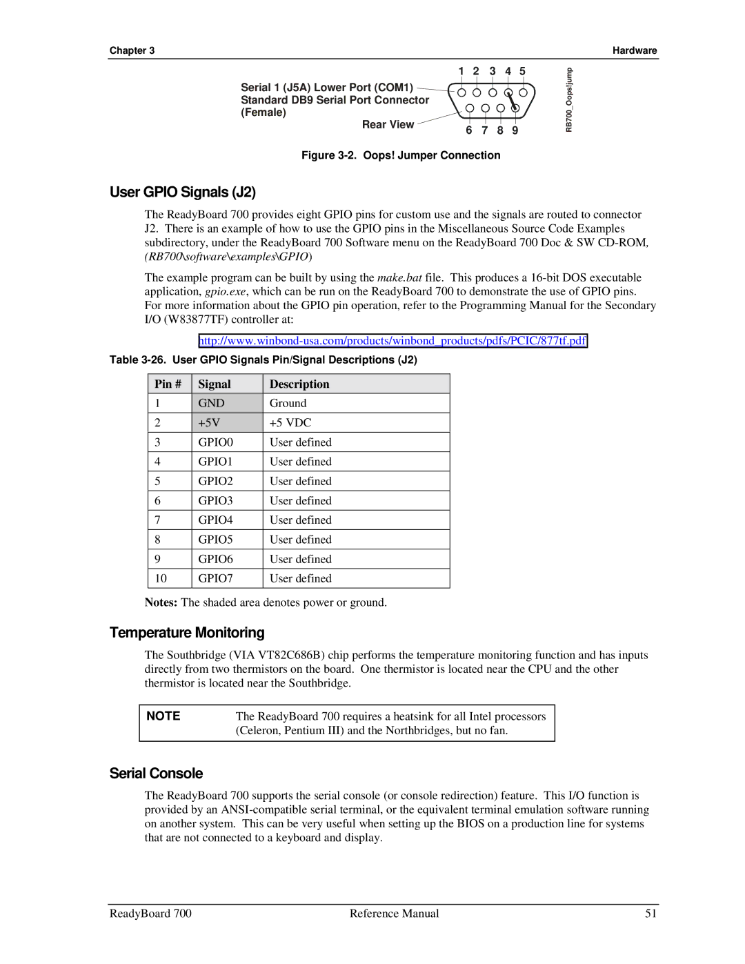
1 2 3 4 5
Serial 1 (J5A) Lower Port (COM1) Standard DB9 Serial Port Connector (Female)
Rear View | 6 | 7 | 8 | 9 |
|
Figure 3-2. Oops! Jumper Connection
RB700_Oops!jump
User GPIO Signals (J2)
The ReadyBoard 700 provides eight GPIO pins for custom use and the signals are routed to connector J2. There is an example of how to use the GPIO pins in the Miscellaneous Source Code Examples subdirectory, under the ReadyBoard 700 Software menu on the ReadyBoard 700 Doc & SW
The example program can be built by using the make.bat file. This produces a
Table
Pin # | Signal | Description |
1 | GND | Ground |
2 | +5V | +5 VDC |
3 | GPIO0 | User defined |
|
|
|
4 | GPIO1 | User defined |
|
|
|
5 | GPIO2 | User defined |
|
|
|
6 | GPIO3 | User defined |
|
|
|
7 | GPIO4 | User defined |
|
|
|
8 | GPIO5 | User defined |
|
|
|
9 | GPIO6 | User defined |
|
|
|
10 | GPIO7 | User defined |
|
|
|
Notes: The shaded area denotes power or ground.
Temperature Monitoring
The Southbridge (VIA VT82C686B) chip performs the temperature monitoring function and has inputs directly from two thermistors on the board. One thermistor is located near the CPU and the other thermistor is located near the Southbridge.
NOTE | The ReadyBoard 700 requires a heatsink for all Intel processors |
| (Celeron, Pentium III) and the Northbridges, but no fan. |
|
|
Serial Console
The ReadyBoard 700 supports the serial console (or console redirection) feature. This I/O function is provided by an
ReadyBoard 700 | Reference Manual | 51 |