Power | Latch, IR Board, and |
BATT | Board |
Ÿ“Battery” on page 61
Ÿ “Hard Disk Drive” on page 62
Ÿ “Combo Bay” on page 63
Ÿ“Keyboard” on page 70
Ÿ “LED Board” on page 72
Ÿ “Upper Heatsink” on page 73
Ÿ “CPU Board” on page 76
Ÿ “LCD Panel” on page 77
Ÿ “Upper Cover” on page 79
Ÿ “IMM Lower Heatsink” on page 81
Ÿ“Fan” on page 82
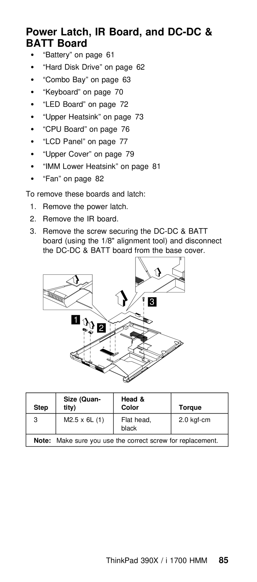
To remove these boards and latch:
1.Remove the power latch.
2.Remove the IR board.
3.Remove the screw securing the
3
1
2
| Size | (Quan- | Head | & |
|
|
|
Step | tity) | Color |
| Torque |
|
| |
|
|
|
|
|
|
|
|
3 | M2.5 | x 6L | (1) Flat | head, | 2.0 |
| |
|
|
| black |
|
|
| |
|
|
|
|
|
|
|
|
Note: | Make | sure | you use | the correct | screw for repl | ||
|
|
|
|
|
|
|
|