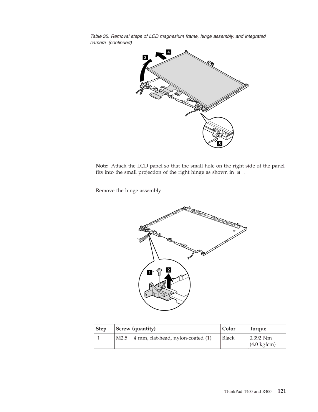
Table 35. Removal steps of LCD magnesium frame, hinge assembly, and integrated camera (continued)
5
Note: Attach the LCD panel so that the small hole on the right side of the panel
fits into the small projection of the right hinge as shown in | . |
Remove the hinge assembly. |
|
1
2
Step | Screw (quantity) | Color | Torque |
|
|
|
|
| M2.5 ⋅ 4 mm, | Black | 0.392 Nm |
|
|
| (4.0 kgfcm) |
|
|
|
|