IBM
Page
IBM
Fourth Edition May
Contents
Part 4. Appendixes
Automatic Printing with APU Monitor
Figures
Vi APU Users Guide
Tables
Viii APU Users Guide
Purpose of this Publication
APU Enhancements
Organization of the Manual
APU Users Guide
Part 1. Understanding and Preparing to Use APU
Introducing Advanced Print Utility
APU Users Guide
What is APU?
Introducing Advanced Print Utility
What You Can Do with APU
Why Use APU?
Printing with and without APU
Printing without APU
Design Phase
Printing with APU
Production Phase
APU formatting instructions
Steps in Creating an APU Document
APU Concepts
Analyzing the Existing Application
Questions you need to Ask
Example of Sample Spooled File Source Input Data
Using APU to Create a Print Definition
Locating Required AFP Resources
LOS
Chantenay Seeds
Printing with the Print Definition
Defining Page Formats
Defining Copies
APU
Introducing Advanced Print Utility
APU Users Guide
Preparing to Use the Advanced Print Utility
APU Prerequisites and Options Required
Recommended
Optional
Initial APU Setup
SUPER2
Input Inch
Font Installation Considerations
Review Document Resource Requirements
Apudft
Calc
Super Sun Seeds Invoice
Using Fonts with APU
Printersville
Map Text panel
Outline Fonts
Default SYS
Custom Fonts
USR, *SYS, *ALL
Display Font Details on Work with Fonts panel
Special Helvetica
Special
Helvet
Image Resources
How APU Works with Image Resources
Strwnb
Treenb
Inch Strwnb
Building Image Resources
Overlay Resources
How APU Works with Overlays
Invall
Invbac Super SUN Seeds T&C Invfst Invoice First
Invoice Full Header
Invlst Invoice Last Invmid Invoice Middle
Building Overlay Resources
Bar Code Resources
Invbac
Code 3 of 9 Bar Code Example
Postnet Postal Bar Code Bar Code Example
How APU Works with Bar Codes
Map Bar Code panel
Postnet
Additional Bar Code Attributes
Part 2. Creating Print Definitions with APU
Building an APU Print Definition for a Single Page Format
APU Users Guide
Building an APU Print Definition for a Single Page Format
Example of a Single-Page Format Document
Example of the SCS File to be Formatted
Setting up a Basic Print Definition
Example of the Formatted File
Identifying Resources
Working with a Print Definition
Work with Print Definitions
Further Defining the Print Definition
SUNSD1
YES, *NO
Qypuoutq
ALL
USER1 Qypuoutq
Invscs USER1 Qypuoutq
Working with Copies
Input
Courier LATIN1
Work with Copies panel
Setting up Duplexing
Selecting a Sample Spooled File
Layout Options
Layout Options You can Set
Defining Page Segments
What Duplex Printing Does
Defining Overlays
Create Page Segment Positioning panel
Mapping Field Data
Invscs
Best WAY
Your Printer RE
High
Spar
Nort
Mapping a Field as Text
Same Performance Boulevard Printersville
Using the Repeat Function
When you map a field, the mapping is displayed as follows
Mapping a Field at Multiple Locations
Mapping a Field the First Time
Mapping a Field to a Second Position
Multiple Mapping Restrictions
Building an APU Print Definition for Multiple Page Formats
Example of a Multiple Page Format Document
Super Sun Seeds Invoice
Building an APU Print Definition for Multiple Page Formats
Overview of Defining a Multiple Page Format Document
Initial Copy for Page Format One
Continuation Page Format
Working with a Print Definition Identifying Resources
Starting to Work on a Print Definition
Developing Your Print Definition
Invoice
YES YES, *NO
Define a Print Definition panel displays
APU1
Set Print Definition Attributes Screen 1 panel
Perelman Qypuoutq RDY Invscs HLD
Defining Selection Fields
Set Print Definition Attributes panel 2 panel
Inside page formats are copies
Defining the Page Layout
Specifying the Back Overlay
Mapping Fields
Back Overlay Terms and Conditions Invbac
Mapping Bar Codes
Organic Garden Supplies
Goldenoats Nochems
Chris Seeder
Map Bar Code panel
Defining Constant Data
Selecting Fonts
Text
Outline Fonts
Define Overlays panel
Replicating the Contents of Copies
Arboles DEL SUR
Seed Roaster Oven SET
Fava Seeds
Purple Teepee Seeds
Continuation Page Copies
Sample Packing List Showing Suppression
PAGE1
Pagen
Create with Copies panel
Packing
USE USE, *OMIT, *GOTO
AND, or
USE PAGE1 Pagen
APU Users Guide
Manual and Command Line Printing
Part 3. Printing With APU
APU Users Guide
Manual and Command Line Printing with APU
Methods of Printing with APU
Manually Associating a Print Definition with a Spooled File
Panel 1 Apply Print Definition
John
Normal
Panel 2 Apply Print Definition
JOB
Spoolfile
NO, *YES
Using the Apply Print Definition Command
Panel 3 Apply Print Definition
Automatic Printing with APU Monitor
Introduction to the APU Monitor
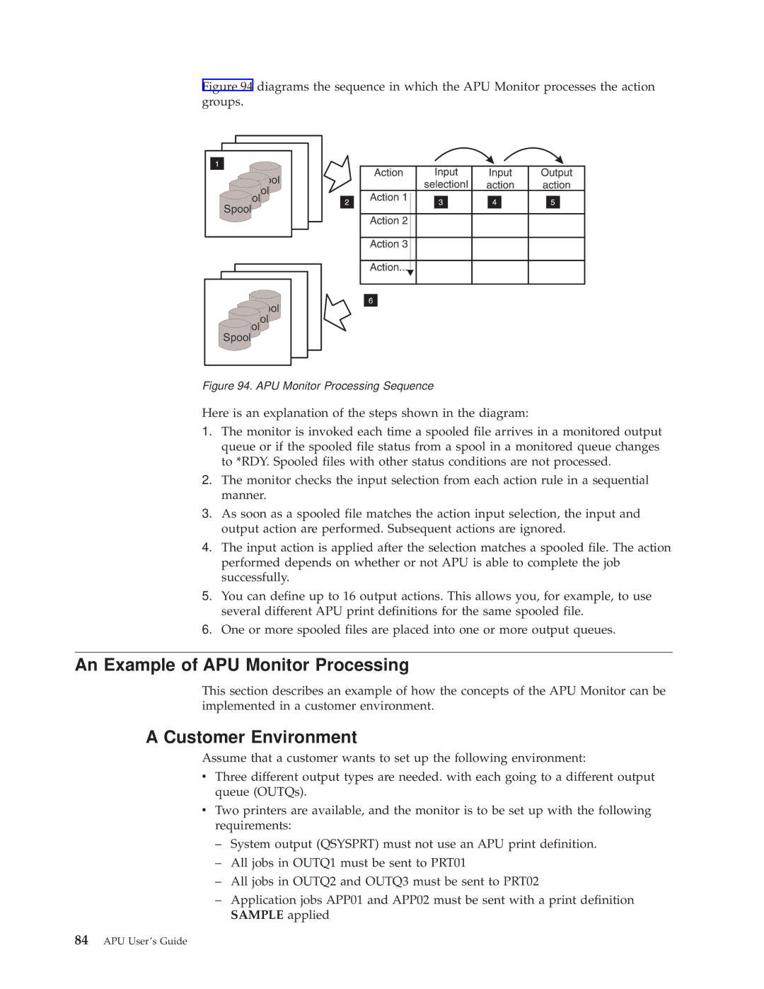
Understanding How the APU Monitor Works
An Example of APU Monitor Processing
Customer Environment
Implementing the Customer Requirements on the APU Monitor
Outq Save
Condition of the Output Queue after Processing
APU Monitor Action Example
Configuring APU Monitor
APU Main Menu
Specifying the Queues APU is to Monitor
Qgpl
Configuring APU Monitor Action
Initial Panel
Creating an Action Group Entry
Defining Selection for Input Spooled File
Defining Action for Input Spooled File
Qpjob
OUTQ1
Defining Action for Output Spooled File
An Example of this Processing Step
Outq
OUT1
Action
Defining User Exit Before and Middle
Spooled File Location after Processing
Sample
Prtdeflib
PRT01
Defining User Exit After
YES, *NO, Spoolfile
Devd
Starting APU Monitor
Begin at the APU Main menu, as shown in Figure
Stopping APU Monitor
Monitor
Part 4. Appendixes
APU Users Guide
Appendix A. APU Samples
Name Type
APU Users Guide
Processing Phases
Appendix B. User Exits
User Exit Before
User Exit Middle
Parameters Passed to the Before Initialization User Exit
User Exit After
Parameters Passed to the Middle User Exit
Sample User Exit Program
VAR&EXPARM
VAR&EXINFILE
VAR&EXINNBR
VAR&RESERVED
VAR&EXINTYPE
VAR&EXJOBUSR
VAR&EXJOBNBR
MSG’APU
Exinfile *TCAT ’.’ *CAT &EXINNBR *BCAT +
HOLD’ *CAT &EXOTHOLD *TCAT ’ SAVE’ +
CAT &EXOTSAVE *TCAT ’’ TOUSR*SYSOPR
Return Endpgm
Apyprtdef Command
APU Defaults
Appendix C. APU Helpful Hints
Maximum APU Values
Mapping Data
Copies and Page Formats
Duplex
Creating Sample Spool Files
Creating Your Own Copy of Invscs
Recreating Invpre and Invscs
APU Users Guide
Appendix D. AFP Resource Commands
Creating Font Resources
Creating Overlay Resources
Fntrsc
Curlib
MBR Fntrsc
Creating Page Segment Resources
OVL
MBR OVL
Datatype Afpds
Pagseg
MBR Pagseg
Appendix D. AFP Resource Commands
APU Users Guide
Appendix E. Rotation Hints
Methods of Rotating Text Data
General Rules
APU Users Guide
Appendix F. Font Samples
Times New Roman Medium
Helvetica Roman Bold
Helvetica Roman Bold
Courier
Courier Font Samples
APU Users Guide
Glossary
127
Bar Code Object Content Architecture Bcoca
Glossary
MICR. Magnetic ink character recognition
Glossary
Spooling simultaneous peripheral operation online
Trademarks
IBM
APU Users Guide
Index
Overlay
Cpysplf
Extaft
Extbef
User exit
APU Users Guide
Readers Comments Ð Wed Like to Hear from You
How satisfied are you that the information in this book is
Business Reply Mail
Page
Ibmr