IR20
Auto write and 50 scan edge channels are included
Some frequency bands are inhibited according to version
May occur
Equipment damage may occur
Operate this device under FCC regulations
Precaution
Supplied Accessories
Table of Contents
Battery pack installation
Batteries installation
Quick Reference Guide
Preparations
Swivel belt clip Option
Belt clip
Third-party antennas may in- crease receiver performance
Antenna
About default setting
Charging the battery
Your first scanning
Experience
Adjusting squelch level
Adjusting audio level
Basic operation
Turning on the receiver
Receive mode selection
Setting frequency
Memory programming
Selecting a memory channel
Programming scan edges Writing a memory channel
Programmed scan operation
Selecting a scan edge channel B
Selecting a scan edge channel a
Cancelling scan
Starting scan Select VFO mode
Starting scan
Selecting a scanning type
Front, top and side panels
Panel Description
ULEFT Dial L-DIAL
EPOWER KEY Power
IRIGHT Dial R-DIAL
QDUALWATCH/CLEAR KEY Dualwatch
MODE/SCAN KEY Mode Scan
Or 10 MHz tuning steps p
VOLUME/DIAL KEY 1 DIAL.SEL
VFO/MHz KEY VFO MHz
Inputs digit ‘5’ for frequency input, memory
Push for 1 sec. to enter the set mode
Inputs digit ‘0’ for frequency input, memory
Inputs digit ‘8’ for frequency input, memory
@2STOP/PLAY ≈
WDUPLEX Indicators p
QBATTERY Indicator
ESIGNAL Squelch Indicators
Function display
TLOCK Indicator p
RANL/NB Indicator pgs
YAFC Indicator p
USKIP Indicators p
Battery installation
Battery INSTALLATION/CHARGING
Battery caution
Battery charging
Regular charging
Charging caution
Rapid charging with the BC-156
CP-18A/E fuse replacement
Mode selection
Frequency and Channel Setting
VFO mode
Memory mode/PreSet*/TV*/Weather† channels
Operating band selection
Available frequency bands
2425
Setting a frequency
Setting a tuning step
Tuning step selection
Using the dial
Using the keypad
Frequency can be directly set via numeral keys
Editting MHz to 1260.240 MHz
Lock function
Receive mode selection
When a signal is received
Setting audio volume
Basic Operation
Receiving
Squelch level setting
Monitor function
Push and hold SQL to monitor the operating frequency
RF gain
Attenuator function
Setting
Duplex operation
Rotate R-DIALto select Duplex
NB/ANL function
AFC function
Select the sweep steps, if desired
Band scope
Single band operation
Dial function assignment
Operating bands table for dualwatch operation
Main band selection Band exchange
Lower band’s squelch adjustment
Setting audio volume Squelch level setting
Memory Channels
Memory channel contents
General description
Memory channel programming
Push MR S.MW for 1 sec. to set the channel into the bank
Memory bank setting
Rotate R-DIALto select the bank channel
Memory bank selection
Rotate R-DIALto select the desired character
Programming memory/bank name
Selecting memory/bank name Indication
Available characters
Dication type from bank name or memory name
Copying memory contents
Memory clearing
Push MR S.MW for 1 sec. to clear the contents
Erasing/transferring bank contents
Scan types
Scan Operation
Full Scan p
FREQUENCY/MEMORY Skip Function p
Select VFO mode with VFO MHz
To start the scan, release Mode Scan
Full/band/programmed scan
Scan edges programming
Release Mode Scan to start the selected scan
Select memory mode with MR S.MW
Memory/bank/all bank scan
To stop the scan, push Dualwatch
During auto-memory write scanning
Auto-memory write scan
Recalling the stored frequencies
Clearing the stored frequencies
Skip channel/frequency setting
Push Dualwatch to exit set mode
Scan pause timer
Scan resume condition
SET
Scan resume timer
Priority Watch
Priority watch types
About priority beep function
Push Dualwatch to cancel the watch
Push Dualwatch to exit set mode and start the watch
Priority watch operation
Select the desired memory channel
VFO scan watch qSelect memory mode
0Push Dualwatch to cancel the watch and scan
While scanning memory/bank channels
Comfortable Receiving
Tone/DTCS squelch operation
Push Dualwatch to stop the beeps and blinking man- ually
Available Dtcs code list
Tone squelch frequency/DTCS code setting
Push 8 SET
Available tone frequency list
Dtcs polarity setting
Push 4 T-SCANfor 1 sec. to start the tone scan
Tone scan
SET Mode
Expanded set mode ON/OFF
General
Set mode items
Expanded set mode items
General set mode items
Key-touch beep
Priority watch
Beep output level
Display backlighting
Noise blanker
Power save
ANL function
AF filter
Power and Lock
No accessible key is available, except
AM antenna selection
FM antenna selection
Default
Auto power OFF
Dial speed acceleration
Monitor key action
Scan resume timer
Scan pause timer
Scan stop beep
Turns the scan stop beep function on and OFF
Offset frequency
Scope audio output
Duplex direction
Sets the audio output function while scope operation
Dtcs code
Tone frequency
Dtcs polarity
Available subaudible tone frequencies
Memory bank link
LCD contrast can be adjusted through 15 levels
LCD contrast
Turns weather alert function on and OFF
CI-V address
CI-V baud rate
CI-V transceive
Other Functions
RPush Dualwatch to exit set mode
Antenna selection
Selecting antenna
Weather channel operation
Turn the weather alert function OFF in set mode
Weather channel selection
Weather alert function
Cloning using a personal computer
Data cloning
Receiver shows following indications
Cloning error
Auto power-off function
Playing back recorded content
IC recorder
Recording a received audio
Recording set mode Quality setting
Playback speed setting
Erasing recorded audio
Automatic recording
REC
Same time, but cannot erase each track independently
Partial reset
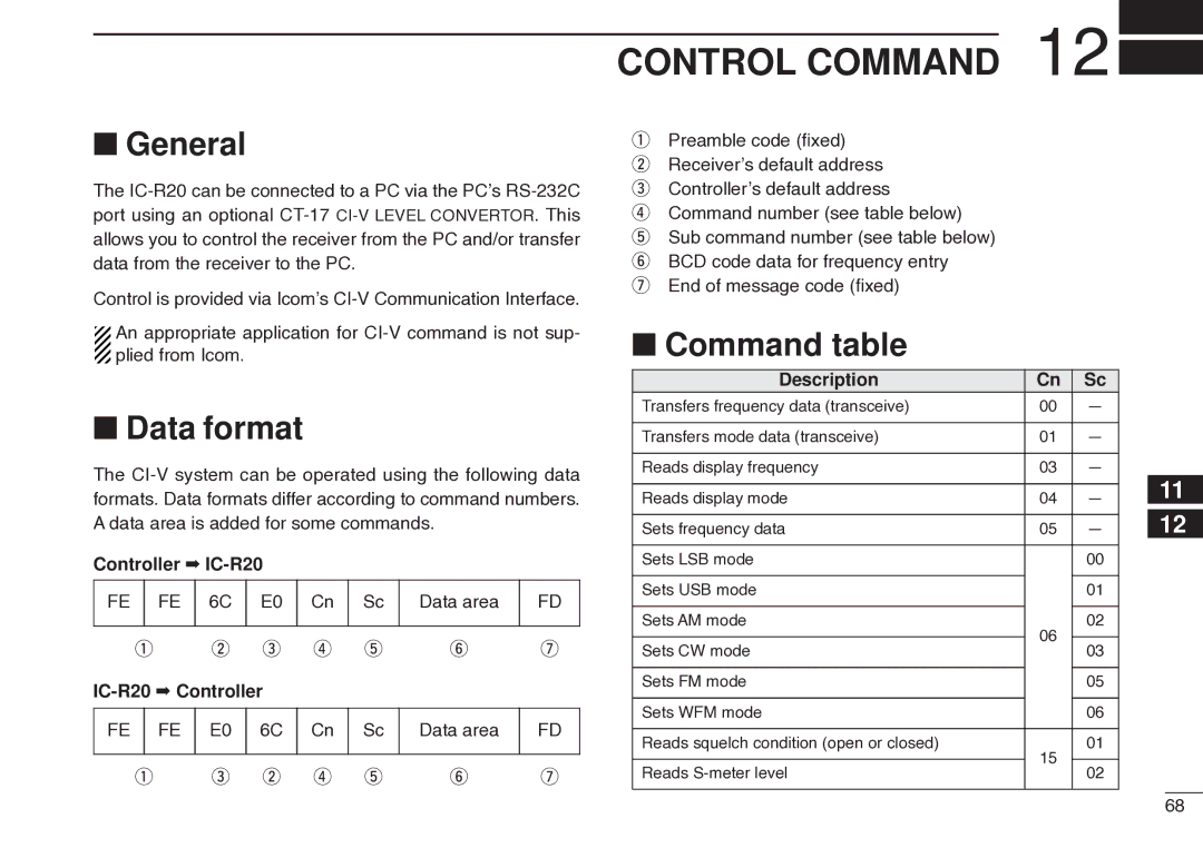
Control Command
Command table
Data format
CI-V compatible transceiver
Control Command
TV channels
Frequency Table
S.A. channels
Ccir channels
New
China channels
Zealand
Channels
Italian channels
Indonesian channels
Taiwan channels
FOT channels
Weather channelsunit MHz
VHF marine channels
Other communications in the USA
Channels Murs channels
HF CB Citizens Band channels
Wireless Microphones
General aviation frequencies
Cable TV IRC
LPD Low Power Device channels Unit MHz
Other communications- other countries
PMR446 channels unit MHz
UHF C.R.S Citizen Radio Service channels
Troubleshooting
Maintenance
General
Specifications
Options
Options
For Microsoft Windows XP
Driver Installation
Driver Installation
Windows starts installing the USB driver
0Repeat step e to y
After the installation is completed, click Finish
For Microsoft Windows
2After clicking Finish, the dialog appears as below
Found New Hardware Wizard will come up as below. Click Next
Select Click
Driver Installation
For Microsoft Windows 98/98SE/Me
Select Click
COM port confirmation
Click the Device Manager
IR20
Pocket Guide
Release Mode Scan to start scan
We Icom Inc. Japan
Declaration Conformity
Kamiminami, Hirano-ku, Osaka 547-0003, Japan
#07 France