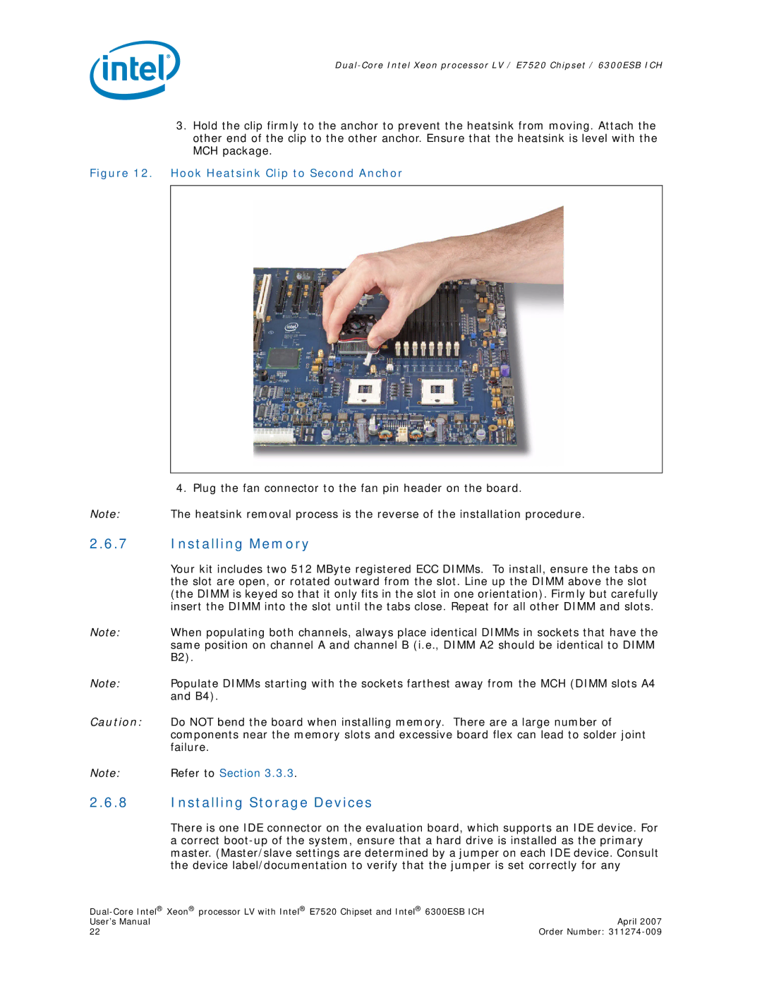
3.Hold the clip firmly to the anchor to prevent the heatsink from moving. Attach the other end of the clip to the other anchor. Ensure that the heatsink is level with the MCH package.
Figure 12. Hook Heatsink Clip to Second Anchor
4. Plug the fan connector to the fan pin header on the board.
Note: The heatsink removal process is the reverse of the installation procedure.
2.6.7Installing Memory
Your kit includes two 512 MByte registered ECC DIMMs. To install, ensure the tabs on the slot are open, or rotated outward from the slot. Line up the DIMM above the slot (the DIMM is keyed so that it only fits in the slot in one orientation). Firmly but carefully insert the DIMM into the slot until the tabs close. Repeat for all other DIMM and slots.
Note: When populating both channels, always place identical DIMMs in sockets that have the same position on channel A and channel B (i.e., DIMM A2 should be identical to DIMM B2).
Note: Populate DIMMs starting with the sockets farthest away from the MCH (DIMM slots A4 and B4).
Caution: Do NOT bend the board when installing memory. There are a large number of components near the memory slots and excessive board flex can lead to solder joint failure.
Note: Refer to Section 3.3.3.
2.6.8Installing Storage Devices
There is one IDE connector on the evaluation board, which supports an IDE device. For a correct
| |
User’s Manual | April 2007 |
22 | Order Number: |