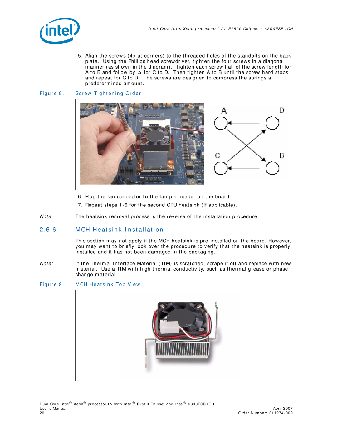
5.Align the screws (4x at corners) to the threaded holes of the standoffs on the back plate. Using the Phillips head screwdriver, tighten the four screws in a diagonal manner (as shown in the diagram). Tighten each screw half of the screw length for A to B and follow by ¼ for C to D. Then tighten A to B until the screw hard stops and repeat for C to D. The screws are designed to compress the springs a predetermined amount.
Figure 8. Screw Tightening Order
6.Plug the fan connector to the fan pin header on the board.
7.Repeat steps
Note: The heatsink removal process is the reverse of the installation procedure.
2.6.6MCH Heatsink Installation
This section may not apply if the MCH heatsink is
Note: If the Thermal Interface Material (TIM) is scratched, scrape it off and replace with new material. Use a TIM with high thermal conductivity, such as thermal grease or phase change material.
Figure 9. MCH Heatsink Top View
| |
User’s Manual | April 2007 |
20 | Order Number: |