6.5SMBUS Headers
The SMBUS headers are used to connect the SMBUS. Refer to the following tables for pinout information.
Table 17 describes the SMBUS 3.3 V STBY pinout.
Table 17. SMBUS 3.3 V STBY Pinout
Pin | Connector Description |
1SMBDAT
2GND
3SMB CLK
6.6Back Panel Connectors
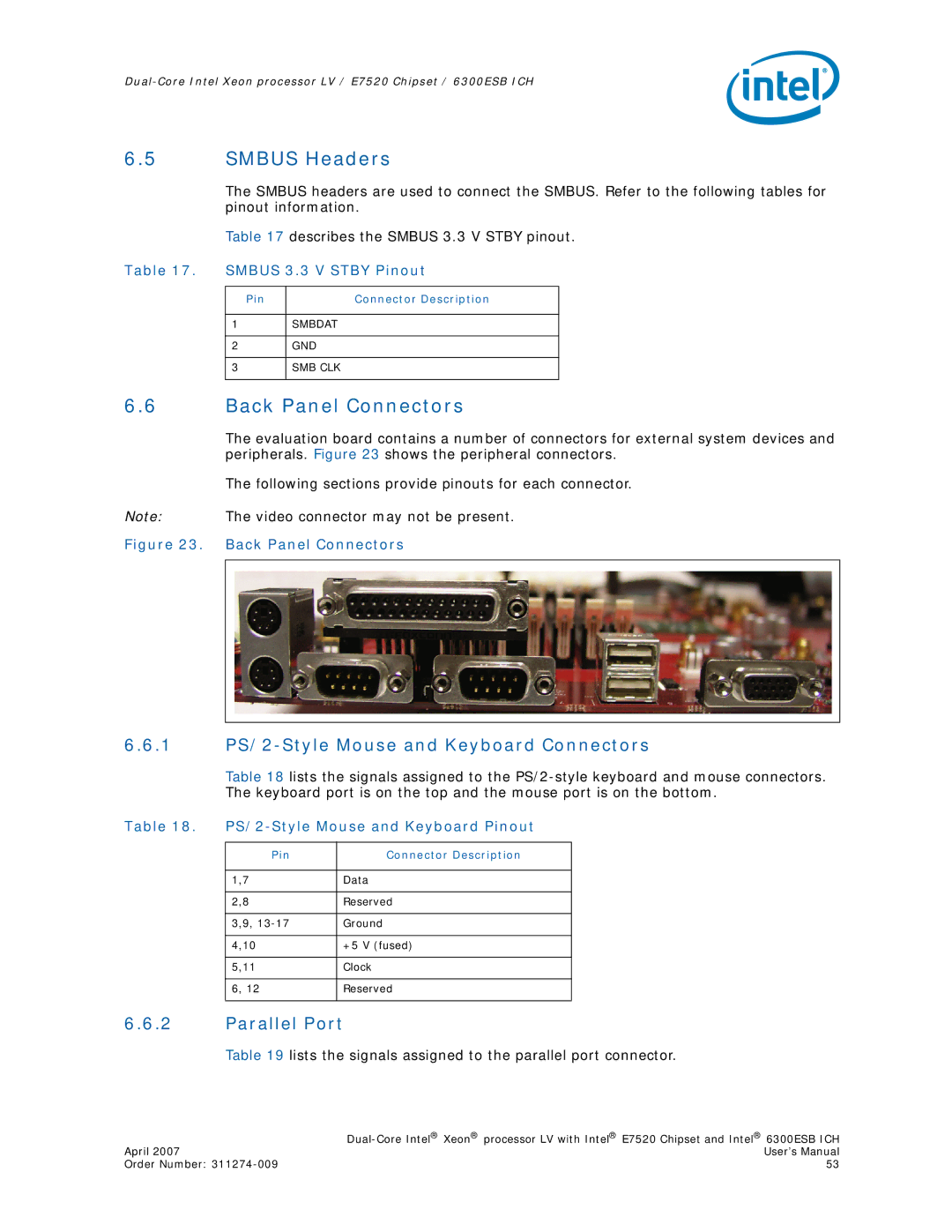
The evaluation board contains a number of connectors for external system devices and peripherals. Figure 23 shows the peripheral connectors.
The following sections provide pinouts for each connector.
Note: The video connector may not be present.
Figure 23. Back Panel Connectors
6.6.1PS/2-Style Mouse and Keyboard Connectors
Table 18 lists the signals assigned to the
Table 18.
Pin | Connector Description |
|
|
1,7 | Data |
|
|
2,8 | Reserved |
|
|
3,9, | Ground |
|
|
4,10 | +5 V (fused) |
|
|
5,11 | Clock |
|
|
6, 12 | Reserved |
|
|
6.6.2Parallel Port
Table 19 lists the signals assigned to the parallel port connector.
| |
April 2007 | User’s Manual |
Order Number: | 53 |
