3.0Theory of Operation
3.1Block Diagram
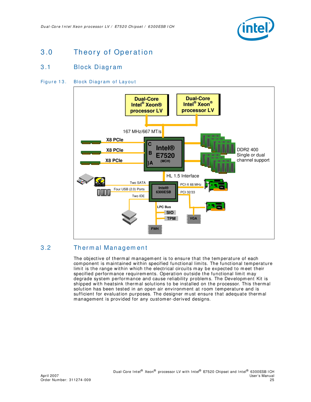
Figure 13. Block Diagram of Layout
Intel® Xeon® processor LV
Intel® Xeon®
processor LV
167 MHz/667 MT/s
|
| X8 PCIe |
|
|
|
|
|
|
|
|
| C Intel® |
|
| |
|
| X8 PCIe |
|
|
| ||
|
|
|
| B E7520 |
|
| |
|
| X8 PCIe |
|
|
| ||
|
|
| }A | (MCH) |
|
| |
|
|
|
|
|
|
| |
|
|
|
|
|
|
| |
|
|
|
|
|
|
|
|
DDR2 400 |
Single or dual |
channel support |
HL 1.5 Interface
Two SATA |
| ||
| Intel® | ||
Four USB (2.0) Ports |
| ||
6300ESB | PCI 32/33 | ||
|
Two IDE
LPC Bus
SIO
TPM
VGA
FWH
3.2Thermal Management
The objective of thermal management is to ensure that the temperature of each component is maintained within specified functional limits. The functional temperature limit is the range within which the electrical circuits may be expected to meet their specified performance requirements. Operation outside the functional limit may degrade system performance and cause reliability problems. The Development Kit is shipped with heatsink thermal solutions to be installed on the processor. This thermal solution has been tested in an open air environment at room temperature and is sufficient for evaluation purposes. The designer must ensure that adequate thermal management is provided for any
| |
April 2007 | User’s Manual |
Order Number: | 25 |