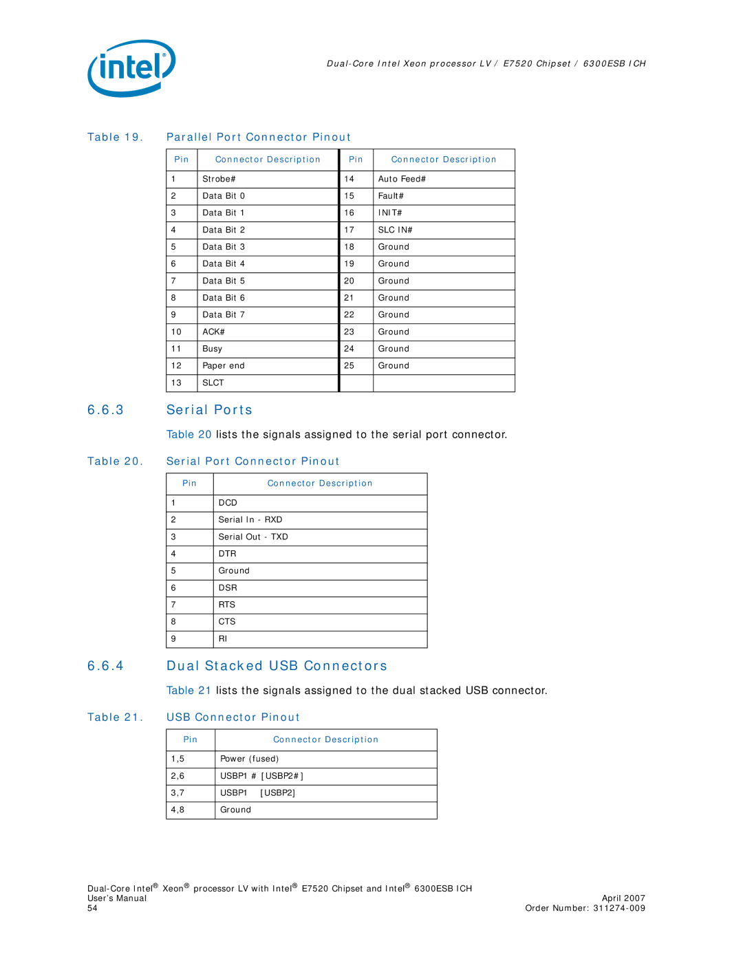
Table 19. Parallel Port Connector Pinout
Pin | Connector Description | Pin | Connector Description |
|
|
|
|
1 | Strobe# | 14 | Auto Feed# |
|
|
|
|
2 | Data Bit 0 | 15 | Fault# |
|
|
|
|
3 | Data Bit 1 | 16 | INIT# |
|
|
|
|
4 | Data Bit 2 | 17 | SLC IN# |
|
|
|
|
5 | Data Bit 3 | 18 | Ground |
|
|
|
|
6 | Data Bit 4 | 19 | Ground |
|
|
|
|
7 | Data Bit 5 | 20 | Ground |
|
|
|
|
8 | Data Bit 6 | 21 | Ground |
|
|
|
|
9 | Data Bit 7 | 22 | Ground |
|
|
|
|
10 | ACK# | 23 | Ground |
|
|
|
|
11 | Busy | 24 | Ground |
|
|
|
|
12 | Paper end | 25 | Ground |
|
|
|
|
13 | SLCT |
|
|
|
|
|
|
6.6.3Serial Ports
| Table 20 lists the signals assigned to the serial port connector. | ||
Table 20. | Serial Port Connector Pinout | ||
|
|
|
|
| Pin | Connector Description |
|
|
|
|
|
| 1 | DCD |
|
|
|
|
|
| 2 | Serial In - RXD |
|
|
|
|
|
| 3 | Serial Out - TXD |
|
|
|
|
|
| 4 | DTR |
|
|
|
|
|
| 5 | Ground |
|
|
|
|
|
| 6 | DSR |
|
|
|
|
|
| 7 | RTS |
|
|
|
|
|
| 8 | CTS |
|
|
|
|
|
| 9 | RI |
|
|
|
|
|
6.6.4Dual Stacked USB Connectors
Table 21 lists the signals assigned to the dual stacked USB connector.
Table 21. USB Connector Pinout
Pin | Connector Description |
|
|
1,5 | Power (fused) |
|
|
2,6 | USBP1 # [USBP2#] |
|
|
3,7 | USBP1 [USBP2] |
|
|
4,8 | Ground |
|
|
| |
User’s Manual | April 2007 |
54 | Order Number: |
