Installing a Serial ATA RAID Controller
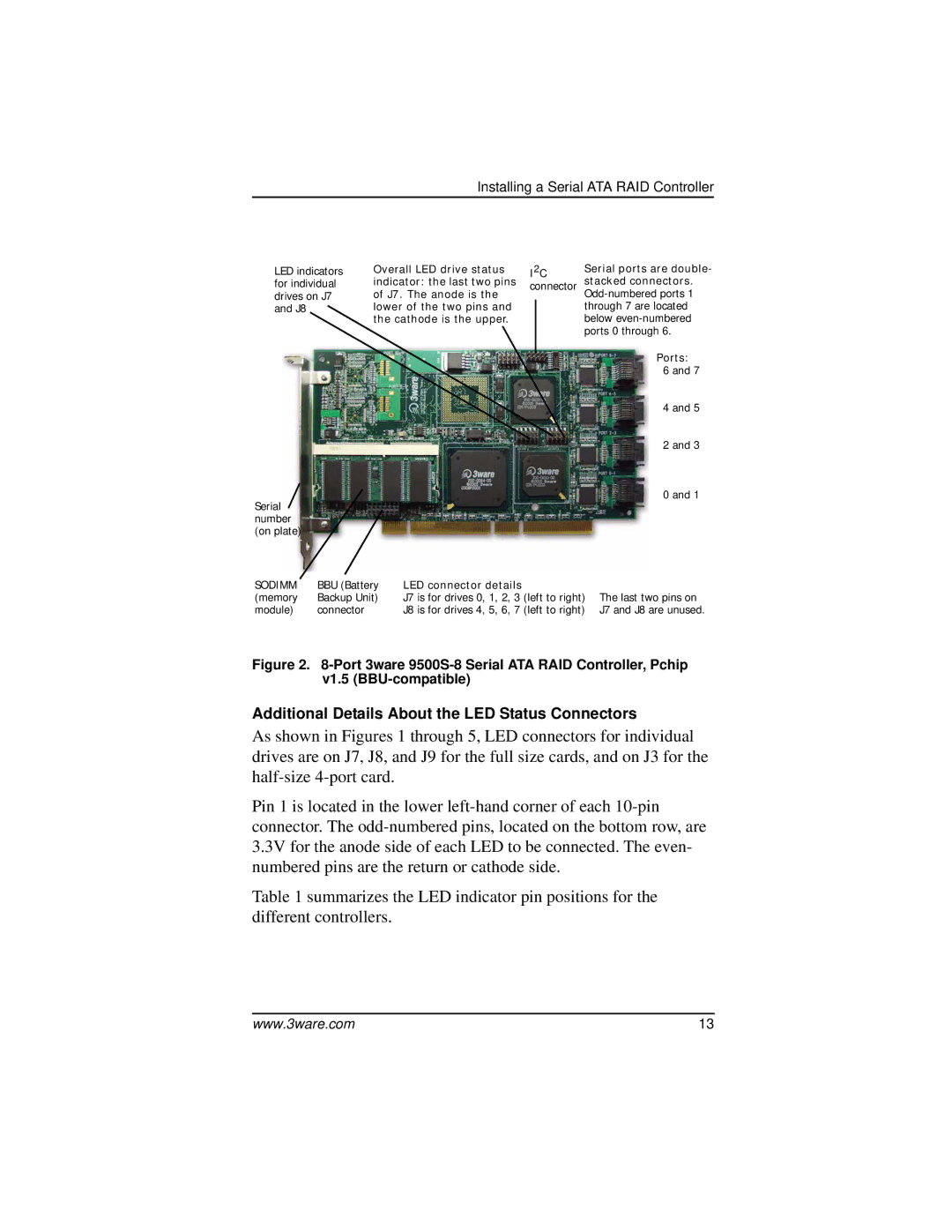
LED indicators | Overall LED drive status | I2C | Serial ports are double- | ||||
for individual | indicator: the last two pins | connector | stacked connectors. | ||||
drives on J7 | of J7. The anode is the | ||||||
and J8 |
| lower of the two pins and |
|
| through 7 are located | ||
|
| the cathode is the upper. |
|
| below | ||
|
|
|
|
|
| ports 0 through 6. | |
|
|
|
|
|
|
| Ports: |
|
|
|
|
|
|
| |
|
|
|
|
|
|
| 6 and 7 |
|
|
|
|
|
|
| 4 and 5 |
|
|
|
|
|
|
| 2 and 3 |
Serial |
|
|
|
|
|
| 0 and 1 |
|
|
|
|
|
|
| |
number |
|
|
|
|
|
|
|
(on plate) |
|
|
|
|
|
|
|
SODIMM | BBU (Battery | LED connector details |
|
|
|
| |
(memory | Backup Unit) | J7 is for drives 0, 1, 2, 3 (left to right) | The last two pins on | ||||
module) | connector |
| J8 is for drives 4, 5, 6, 7 (left to right) | J7 and J8 are unused. | |||
Figure 2. 8-Port 3ware 9500S-8 Serial ATA RAID Controller, Pchip v1.5 (BBU-compatible)
Additional Details About the LED Status Connectors
As shown in Figures 1 through 5, LED connectors for individual drives are on J7, J8, and J9 for the full size cards, and on J3 for the
Pin 1 is located in the lower
Table 1 summarizes the LED indicator pin positions for the different controllers.
www.3ware.com | 13 |