Installing the Hardware
Installing a Serial ATA RAID Controller
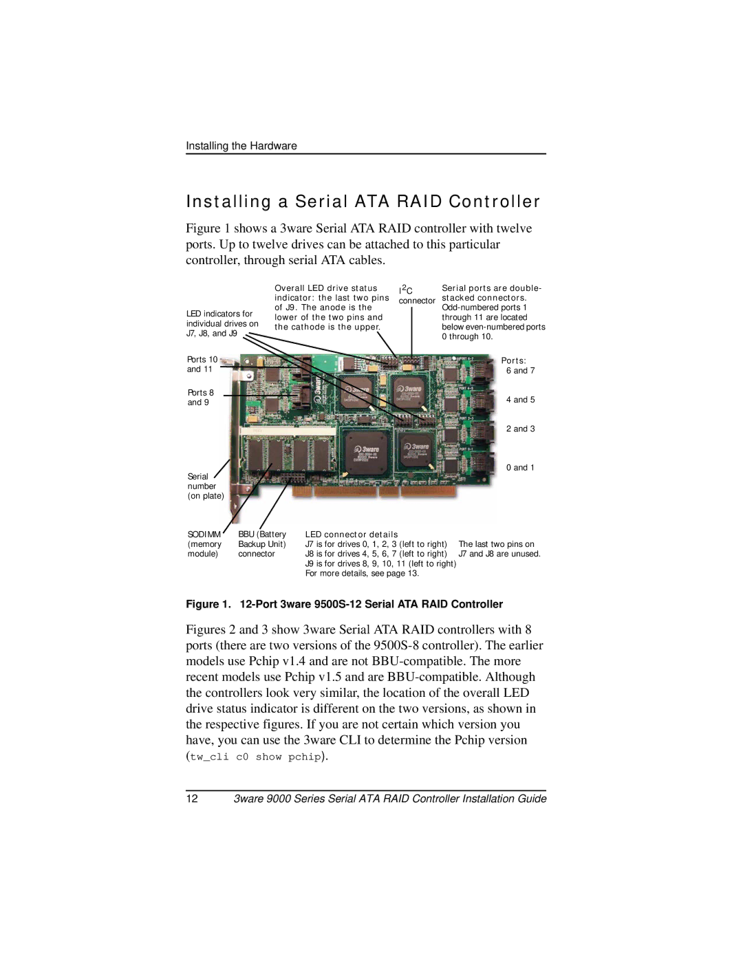
Figure 1 shows a 3ware Serial ATA RAID controller with twelve ports. Up to twelve drives can be attached to this particular controller, through serial ATA cables.
|
|
| Overall LED drive status | I2C | Serial ports are double- | |||
|
|
| indicator: the last two pins | connector | stacked connectors. | |||
LED indicators for | of J9. The anode is the |
|
| |||||
|
| |||||||
lower of the two pins and |
|
| through 11 are located | |||||
individual drives on |
|
| ||||||
the cathode is the upper. |
|
| below | |||||
J7, J8, and J9 |
|
|
| |||||
|
|
|
|
| 0 through 10. | |||
|
|
|
|
|
|
| ||
Ports 10 |
|
|
|
|
|
| Ports: | |
|
|
|
|
|
| |||
and 11 |
|
|
|
|
|
| 6 and 7 | |
Ports 8 |
|
|
|
|
|
|
| 4 and 5 |
and 9 |
|
|
|
|
|
| ||
|
|
|
|
|
|
| ||
|
|
|
|
|
|
|
| 2 and 3 |
Serial |
|
|
|
|
|
| 0 and 1 | |
|
|
|
|
|
|
| ||
number |
|
|
|
|
|
|
| |
(on plate) |
|
|
|
|
|
|
| |
SODIMM | BBU (Battery | LED connector details |
|
|
|
| ||
(memory | Backup Unit) | J7 is for drives 0, 1, 2, 3 (left to right) | The last two pins on | |||||
module) | connector | J8 is for drives 4, 5, 6, 7 (left to right) | J7 and J8 are unused. | |||||
|
|
|
| J9 is for drives 8, 9, 10, 11 (left to right) |
| |||
|
|
|
| For more details, see page 13. |
|
| ||
Figure 1. |
| |||||||
Figures 2 and 3 show 3ware Serial ATA RAID controllers with 8 ports (there are two versions of the 9500S-8 controller). The earlier models use Pchip v1.4 and are not BBU-compatible. The more recent models use Pchip v1.5 and are BBU-compatible. Although the controllers look very similar, the location of the overall LED drive status indicator is different on the two versions, as shown in the respective figures. If you are not certain which version you have, you can use the 3ware CLI to determine the Pchip version
(tw_cli c0 show pchip).
123ware 9000 Series Serial ATA RAID Controller Installation Guide