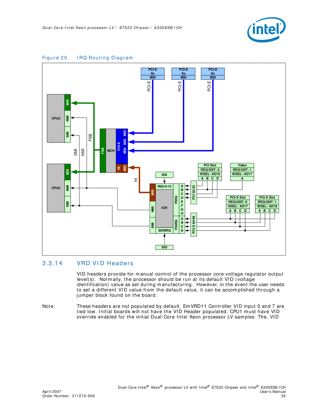
Figure 20. IRQ Routing Diagram
| MSI |
|
CPU0 | NMI |
|
|
| |
| SMI | FSB |
| SMI | NMI |
FSB
MCH
| MSI |
MSI MSI |
|
|
| ||||||
| 8x |
| 8x |
| 8x | |||
| MSI |
| MSI |
| MSI | |||
|
|
|
|
|
|
| ||
|
|
|
|
|
|
|
|
|
|
|
|
|
|
|
|
|
|
|
|
|
|
|
|
|
|
|
| MSI |
|
|
CPU0 | NMI |
| |
|
|
| SMI |
|
|
| HI | MSI |
|
|
| HI | |||
|
|
|
| |
|
|
|
|
|
| IDE |
|
|
|
|
| |
|
|
|
|
|
|
|
|
|
|
|
|
|
|
|
|
MSI | IRQ14/15 | PIRQ | A |
| PCI32/33 | ||
| |||||||
|
| E |
| ||||
|
|
|
| B |
|
| |
|
|
|
| C |
|
| |
|
|
|
| D |
|
| |
|
|
|
|
|
| ||
|
|
|
| F |
|
| |
NMI | ICH |
|
|
| |||
|
|
| |||||
| G |
|
| ||||
|
|
|
| ||||
|
|
|
|
|
| ||
|
|
|
| H |
|
| |
|
|
|
|
|
| ||
| PXIRQ | A | |
| B | ||
| C | ||
SERIRQ | D | ||
SMI |
|
PCI Slot | Video |
REQ/GNT: 0 | REQ/GNT: 1 |
IDSEL: AD16 | IDSEL: AD17 |
A B C D | A |
REQ/GNT: 0 |
IDSEL: AD17 |
A B C D |
REQ/GNT: 1 |
IDSEL: AD18 |
A B C D |
SIO
3.3.14VRD VID Headers
VID headers provide for manual control of the processor core voltage regulator output level(s). Normally, the processor should be run at its default VID (voltage identification) value as set during manufacturing. However, in the event the user needs to set a different VID value from the default value, it can be accomplished through a jumper block found on the board.
Note: These headers are not populated by default. EmVRD11 Controller VID input 0 and 7 are tied low. Initial boards will not have the VID Header populated, CPU1 must have VID override enabled for the initial
| |
April 2007 | User’s Manual |
Order Number: | 35 |
