Intel® IQ80219 General Purpose PCI Processor Evaluation Platform
Hardware Reference Section
3.10.4Jumper Summary
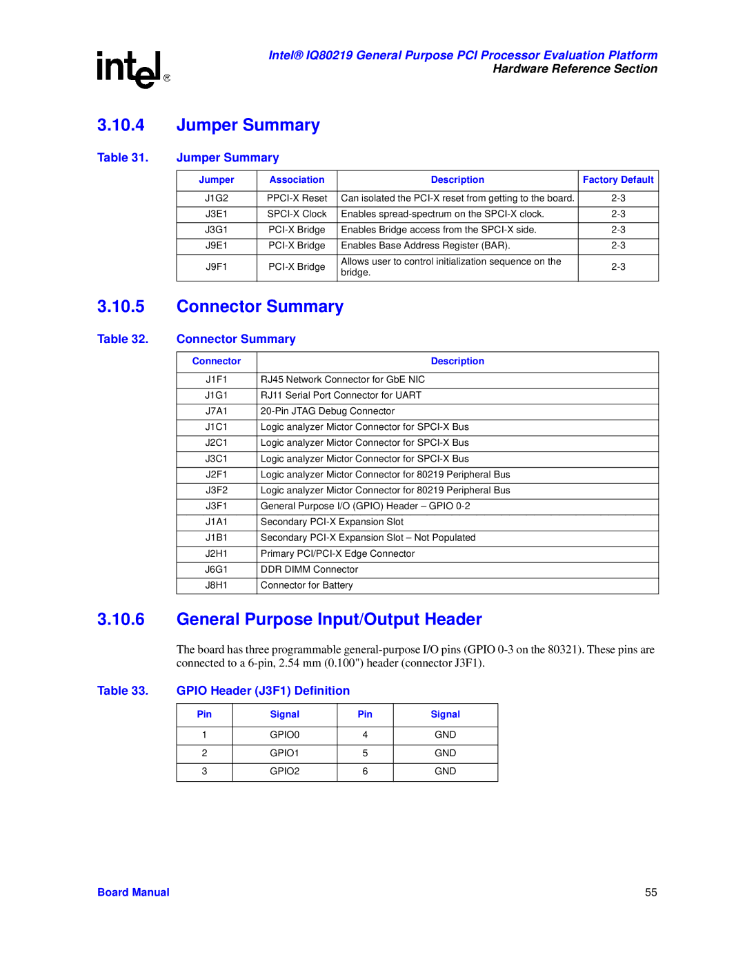
Table 31. | Jumper Summary |
|
| |
|
|
|
|
|
| Jumper | Association | Description | Factory Default |
|
|
|
|
|
| J1G2 | Can isolated the | ||
|
|
|
|
|
| J3E1 | Enables | ||
|
|
|
|
|
| J3G1 | Enables Bridge access from the | ||
|
|
|
|
|
| J9E1 | Enables Base Address Register (BAR). | ||
|
|
|
|
|
| J9F1 | Allows user to control initialization sequence on the | ||
| bridge. | |||
|
|
|
| |
|
|
|
|
|
3.10.5Connector Summary
Table 32. | Connector Summary | |
|
|
|
| Connector | Description |
|
|
|
| J1F1 | RJ45 Network Connector for GbE NIC |
|
|
|
| J1G1 | RJ11 Serial Port Connector for UART |
|
|
|
| J7A1 | |
|
|
|
| J1C1 | Logic analyzer Mictor Connector for |
|
|
|
| J2C1 | Logic analyzer Mictor Connector for |
|
|
|
| J3C1 | Logic analyzer Mictor Connector for |
|
|
|
| J2F1 | Logic analyzer Mictor Connector for 80219 Peripheral Bus |
|
|
|
| J3F2 | Logic analyzer Mictor Connector for 80219 Peripheral Bus |
|
|
|
| J3F1 | General Purpose I/O (GPIO) Header – GPIO |
|
|
|
| J1A1 | Secondary |
|
|
|
| J1B1 | Secondary |
|
|
|
| J2H1 | Primary |
|
|
|
| J6G1 | DDR DIMM Connector |
|
|
|
| J8H1 | Connector for Battery |
|
|
|
3.10.6General Purpose Input/Output Header
The board has three programmable
Table 33. | GPIO Header (J3F1) Definition |
|
| ||
|
|
|
|
|
|
| Pin | Signal |
| Pin | Signal |
|
|
|
|
|
|
| 1 | GPIO0 |
| 4 | GND |
|
|
|
|
|
|
| 2 | GPIO1 |
| 5 | GND |
|
|
|
|
|
|
| 3 | GPIO2 |
| 6 | GND |
|
|
|
|
|
|
Board Manual | 55 |
