November 13
Board Manual
Board Manual
Contents
Debug Interface
Dram
Exploring the CodeLab Debug Windows 100
119
Figures
Tables
Rstmode and Retry Operation Setting Summary
105
Date Revision Description
Revision History
This Page Left Intentionally Blank
Related Documents
Document Purpose and Scope
Component Reference
Electronic Information
Component References
Electronic Information
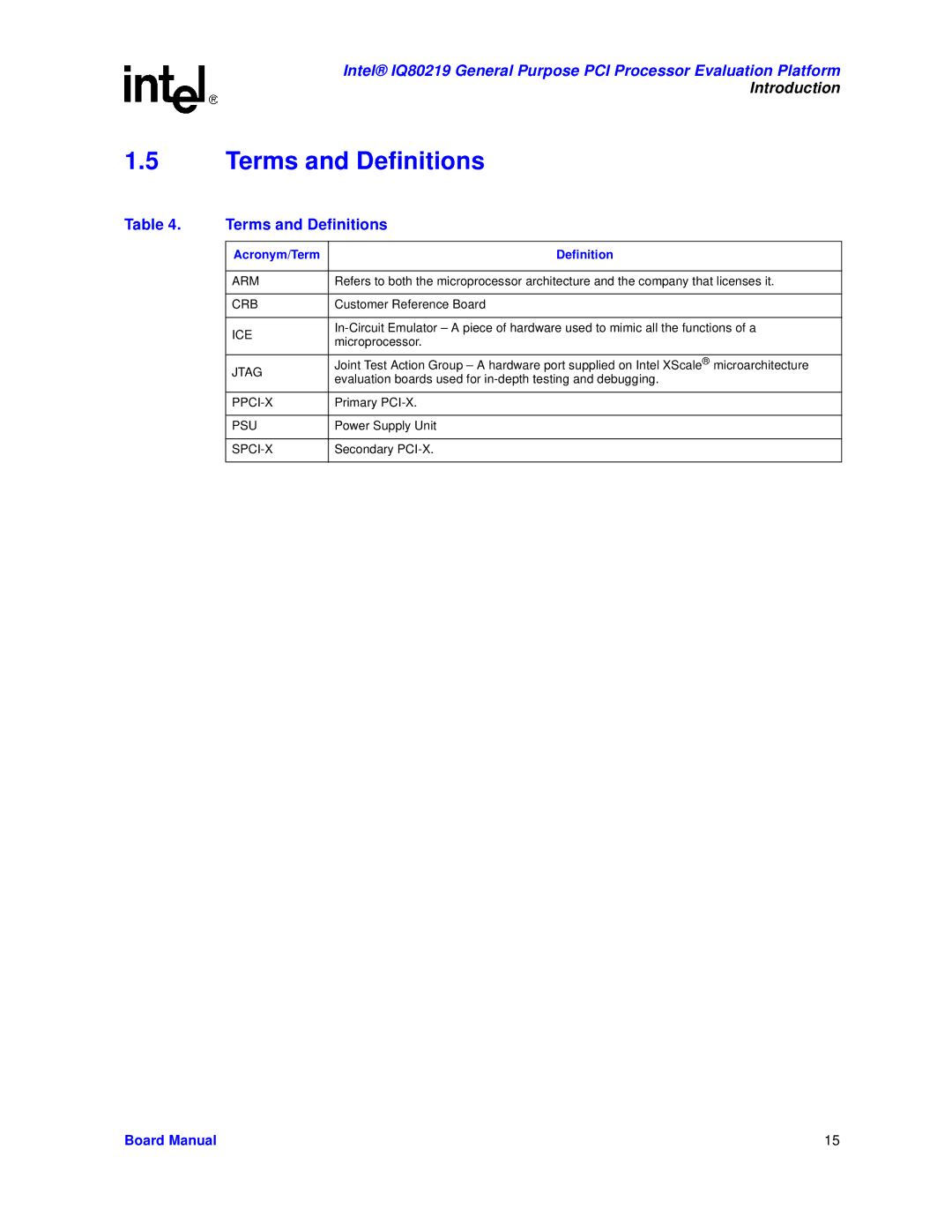
Terms and Definitions
Terms and Definitions
Definition
Intel 80219 General Purpose PCI Processor
Intel 80219 General Purpose PCI Processor Block Diagram
Introduction
Intel IQ80219 Evaluation Platform Board Features
Summary of Features
Feature Definition
Power and Backplane Requirements
Kit Content
Hardware Installation
First-Time Installation and Test
Supported Tool Buckets
Factory Settings
Contents of the Flash
Development Strategy
Target Monitors
Redhat Redboot
ARM Firmware Suite
Semihosting File I/O
ARM Angel
Host Communications Examples
Serial-UART Communication
Ethernet-Network Communication
Jtag Debug Communication
Jtag Debug Communication
GNUPro GDB/Insight
Communicating with Redboot
Getting Started
GDB set remotebaud
Connecting with GDB
ARM Extended Debugger
This Page Left Intentionally Blank
Bridge
Functional Diagram
Intel fi
Giga Ethernet
Board Form-Factor/Connectivity
Form-Factor/Connectivity Features
Power Features
Power
Supported Dimm Types
Battery Backup
DDR Memory Features
Memory Subsystem
Flash Memory Requirements
Flash Memory Requirements
Intel 80219 General Purpose PCI Processor Operation Mode
IQ80219 Interrupt routing
Interrupt Routing
Intel IQ80219 Evaluation Platform Board Peripheral Bus
Peripheral Bus Features
Flash ROM
Flash ROM Features
Uart
Uart Features
HEX Display on the Peripheral Bus
HEX Display
Rotary Switch Requirements
Rotary Switch
Battery Status Buffer Requirements
Battery Status
Intel 82544EI Gigabit Ethernet Controller
Debug Interface
Console Serial Port
Ethernet Port
Jtag Port Pin-out
Logic-Analyzer Connectors
Jtag Debug
3.1 Jtag Port
Mictor J3F2
Micor J3F2 Signal/Pins
Micor J2F1 Signal/Pins
Schematic Signal Name
Mictor J2F1
Mictor J1C1
Micor J1C1 Signal/Pins
Mictor J3C1
Micor J3C1 Signal/Pins
Mictor J2C1
Micor J2C1 Signal/Pins
Reset Requirements/Schemes
Board Reset Scheme
Switch Summary
Switches and Jumpers
User Defined Switches
PCI-X Bridge Initialization Signals
Pcix Initialization Summary
Default Switch Settings Visual
Connector Summary
Jumper Summary
General Purpose Input/Output Header
S9E1-1 S9E1-2 S9E1-3 S9E1-4 S8E1-6 Operation Mode
Secondary PCI/PCI-X Operation Settings
Primary PCI/PCI-X Operation Settings
Primary PCI/PCI-X Operation Settings
Switch S7E1- 2/3
Detail Descriptions of Switches/Jumpers
Switch S7E1- 6/7
Switch S7E1- 4/5
S7E1-8
Switch S7E1
Switch S7E1 8 Descriptions
Switch S7E1 8 Settings and Operation Mode
Switch S8E1
Switch S8E1 6 Descriptions
Switch S8E1 5 Descriptions
Switch S8E1 5 Settings and Operation Mode
Switch S8E1 5 Driver Mode Output Impedances
Switch S8E1 8 Settings and Operation Mode
Switch S8E1 7 Descriptions
Switch S8E1 7 Settings and Operation Mode
Switch S8E1 8 Descriptions
Switch S8E2
Switch S8E2 1/2
Switch S9E1 4 Descriptions
Switch S9E1
Switch S9E1 13 Descriptions
Switch S9E1 13 Settings and Operation Mode
Switch S1D1 1/2
Switch S4D1 1/2
Switch S4D1 3/4
Jumper J1G2
Jumper J3E1
Jumper J3G1
Jumper J9F1
Jumper J9E1
This Page Left Intentionally Blank
Private Device Configuration
Private Device Configuration Requirements
Idsel Routing for Private Device Configuration
Interrupt Routing for Secondary PCI-X Private Device
Interrupt Routing for Private Device Configuration
Dram
Components on the Peripheral Bus
DDR Memory Bias Voltage Minimum/Maximum Values
Software Reference
Address Read Register Write Register
Uart Register Settings
Hex Display Connection to Peripheral Bus
Register Bitmap 7-Segment Display LSB FE85 0000h Write Only
Ethernet
Board Support Package BSP Examples
Intel 80219 General Purpose PCI Processor Memory Map
Intel General Purpose PCI Processor Memory Map
Physical Address Range Description
Redboot* Intel IQ80219 Memory Map
Redboot Intel IQ80310 Physical Memory Map
Redboot Intel IQ80219 Physical Memory Map Visual
Redboot Intel IQ80310 Virtual Memory Map
Redboot Intel IQ80219 Virtual Memory Map Visual
Redboot Intel IQ80219 Files
Redboot Intel IQ80219 DDR Memory Initialization Sequence
Redboot Switching
This Page Left Intentionally Blank
IQ80310 and IQ80219 Comparisons
This Page Left Intentionally Blank
Introduction
Purpose
Necessary Hardware and Software
Related Web Sites
Hardware Setup
Setup
Software Flow Diagram
Software Setup
Creating a New Project
New Project Setup
Configuration
Overview
Flashing with Jtag
Using Flash Programmer
Building an Executable File From Example Code
Debugging Out of Flash
Running the CodeLab Debugger
Launching and Configuring Debugger
Displaying Source Code
Manually Loading and Executing an Application Program
Using Breakpoints
Stepping Through the Code
Setting CodeLab Debug Options
Exploring the CodeLab Debug Windows