SECTION
2.Loosen, but DO NOT remove, the two exterior button screws that secure the footplate assembly to the T‐nuts.
3.Loosen, but DO NOT remove, the two button screws that secure the heel loop to the T‐nuts.
4.Slide footplate assembly up or down, until desired height is achieved.
5.While holding footplate assembly in position, tighten all six button screws that were loosened in STEPS 1‐3.
6.Repeat STEPS 1‐5 for opposite footplate if necessary.
NOTE: If this procedure does not provide enough length, adjust the length of the power legrest. Refer to Adjusting the Length for Power Legrest on page 39.
| Outside View | Inside View | ||
| Exterior Rail |
|
| |
| Channel | Exterior Rail |
| |
|
| |||
|
|
| ||
|
| Channel |
| |
|
|
| ||
|
|
| Button Screws | |
Exterior |
|
| for Heel Loop | |
Footplate |
| Interior Button | ||
Button Screws | Footplate Assembly | |||
Assembly | ||||
| Screws | |||
|
|
| ||
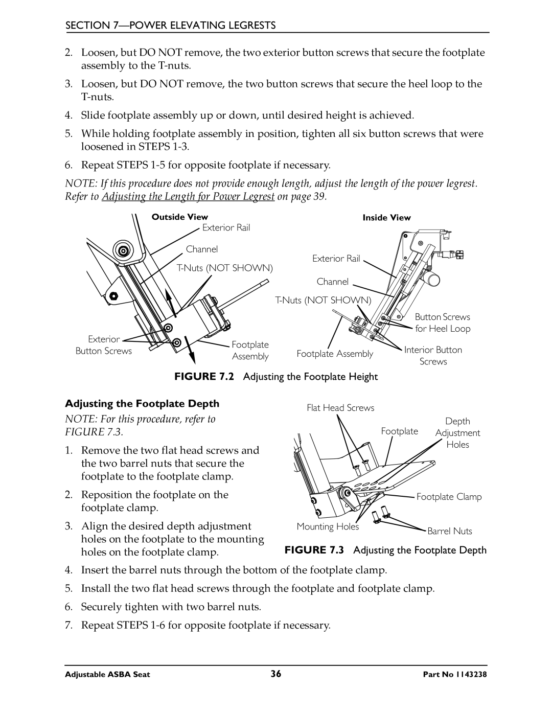
FIGURE 7.2 Adjusting the Footplate Height
Adjusting the Footplate Depth
NOTE: For this procedure, refer to FIGURE 7.3.
1.Remove the two flat head screws and the two barrel nuts that secure the footplate to the footplate clamp.
2.Reposition the footplate on the footplate clamp.
3.Align the desired depth adjustment holes on the footplate to the mounting holes on the footplate clamp.
Flat Head Screws
Depth
Footplate Adjustment
Holes
![]()
![]()
![]()
![]()
![]() Footplate Clamp
Footplate Clamp
Mounting Holes | Barrel Nuts |
|
FIGURE 7.3 Adjusting the Footplate Depth
4.Insert the barrel nuts through the bottom of the footplate clamp.
5.Install the two flat head screws through the footplate and footplate clamp.
6.Securely tighten with two barrel nuts.
7.Repeat STEPS 1‐6 for opposite footplate if necessary.
Adjustable ASBA Seat | 36 | Part No 1143238 |