Page 6
TM-4200GE Software
2 Connectors
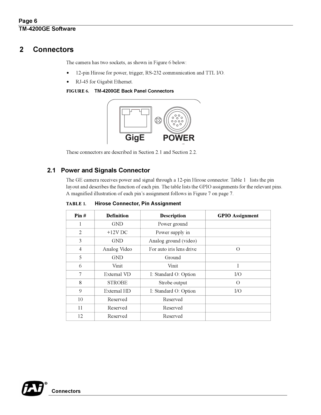
The camera has two sockets, as shown in Figure 6 below:
•
•
FIGURE 6. TM-4200GE Back Panel Connectors
GigE POWER
These connectors are described in Section 2.1 and Section 2.2.
2.1 Power and Signals Connector
The GE camera receives power and signal through a
TABLE 1. | Hirose Connector, Pin Assignment |
| |
|
|
|
|
Pin # | Definition | Description | GPIO Assignment |
|
|
|
|
1 | GND | Power ground |
|
|
|
|
|
2 | +12V DC | Power supply in |
|
|
|
|
|
3 | GND | Analog ground (video) |
|
|
|
|
|
4 | Analog Video | For auto iris lens drive | O |
|
|
|
|
5 | GND | Ground |
|
|
|
|
|
6 | Vinit | Vinit | I |
|
|
|
|
7 | External VD | I: Standard O: Option | I/O |
|
|
|
|
8 | STROBE | Strobe output | O |
|
|
|
|
9 | External HD | I: Standard O: Option | I/O |
|
|
|
|
10 | Reserved | Reserved |
|
|
|
|
|
11 | Reserved | Reserved |
|
|
|
|
|
12 | Reserved | Reserved |
|
|
|
|
|