Page 22
TM-4200GE Software
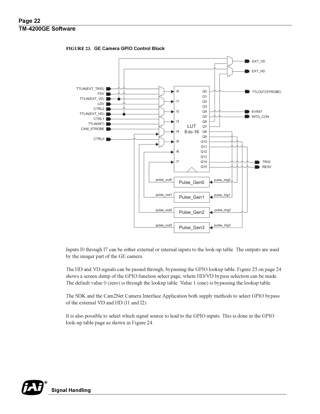
FIGURE 23. GE Camera GPIO Control Block
TTLIN(EXT_TRIG) |
|
|
|
I0 |
| Q0 |
|
FDV |
| Q1 |
|
TTLIN(EXT_VD) |
|
| |
|
|
| |
I1 |
| Q2 |
|
LDV |
| Q3 |
|
CTRL2 |
|
| |
|
|
| |
I2 |
| Q4 |
|
TTLIN(EXT_HD) |
| Q5 |
|
CTRL1 |
|
| |
|
|
| |
I3 |
| Q6 |
|
TTLN(INT) | LUT | Q7 |
|
CAM_STROBE |
| ||
|
| ||
I4 | Q8 |
| |
CTRL0 |
| Q9 |
|
|
|
| |
I5 |
| Q10 |
|
|
| Q11 |
|
I6 |
| Q12 |
|
|
| Q13 |
|
I7 |
| Q14 |
|
|
| Q15 |
|
pulse_out0 |
|
| pulse_trig0 |
Pulse_Gen0 |
| ||
pulse_out1 | Pulse_Gen1 | pulse_trig1 | |
|
| ||
pulse_out2 | Pulse_Gen2 | pulse_trig2 | |
|
| ||
pulse_out3 | Pulse_Gen3 | pulse_trig3 | |
|
| ||
EXT_VD
EXT_HD
TTLOUT(STROBE)
![]() EVINIT
EVINIT
![]() INTG_CON
INTG_CON
TRIG
RESV
Inputs I0 through I7 can be either external or internal inputs to the
The HD and VD signals can be passed through, bypassing the GPIO lookup table. Figure 25 on page 24 shows a screen dump of the GPIO function select page, where HD/VD bypass selection can be made. The default value 0 (zero) is through the lookup table. Value 1 (one) is bypassing the lookup table.
The SDK and the Cam2Net Camera Interface Application both supply methods to select GPIO bypass of the external VD and HD (I1 and I2).
It is also possible to select which signal source to lead to the GPIO inputs. This is done in the GPIO