XV-DDV1SL
Important for Laser Products
Moisture condensation
Precautions for the HDD
Before using the unit
While using the unit
Precautions on the built-in DVD player
Contents
Front view
How to open and close the front panel
Display window
Rear view
Remote control
To set the TV’s brand code
Installing batteries
Controlling the TV using remote control
Precautions for the safe use of batteries
TVs Codes
Usable buttons for operating the TV
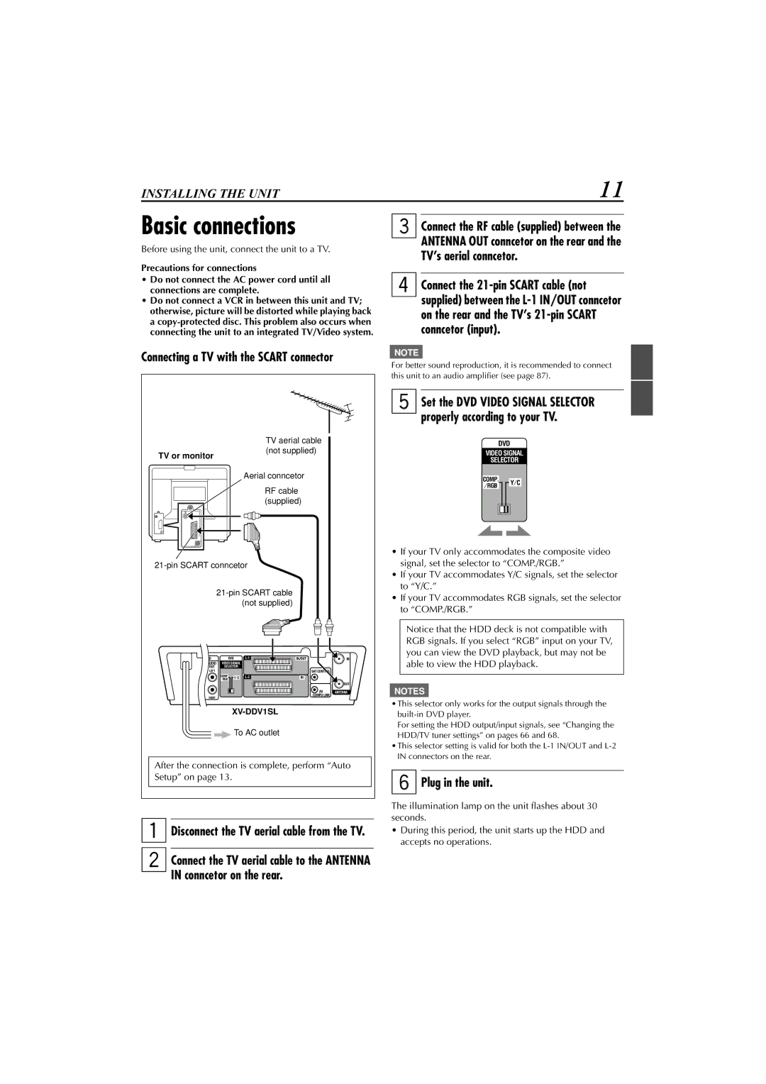
Disconnect the TV aerial cable from the TV
Connecting a TV with the Scart connector
Basic connections
Plug in the unit
Connecting a TV with the audio/video jacks
Precautions on connecting the power cord
Turn on the power
Easy & simple setup
Presetting the built-in TV tuner
Automatically-Auto Setup
Press 5 or to move to T-V LINK, then press Enter or
Start TV-linked Setup
Unit sets the clock time and Guide Program
Auto Standby
TV Auto Power On
You can use your TV’s remote control to turn off the unit
What you can do with T-V Link
Before performing any operations
Selecting the playback source
About the opening screen
Make connections
Installing satellite controller
Situate the satellite controller
Attach the satellite controller
Select the Sat Control Set screen
Show the Main Setup screen on the unit
Turn on the satellite receiver
Select the Initial Set screen
Brand name Code
Check what happened on the satellite receiver
Select the DVD player
DVD Initial Setup
Show the DVD Player SET UP screen
To bring up the DVD Player SET UP screen later
Press HDD/TV PR +/- repeatedly or the number buttons
What is Live Memory
Select the HDD deck
Choose a programme
To record Nicam bilingual programmes
Receiving stereo and bilingual programmes
To go back to a previous scene quickly and play it back
To change the sound you hear
Start recording
On the remote control only
Basic recording
Set the recording speed
Watching another programme while recording
Instant Timer Recording ITR
Changing the recording speed
To stop recording
To stop playback
Basic playback
Start playback
To stop playback temporarily Playback Pause
Skipping forward quickly-Quick Skip
While playing, press on the remote control
Searching for a particular scene-Variable Speed Search
While playing or recording, press ¢ cursor 3 or Or cursor
This feature is also available during recording
Playing in slow motion-Slow Motion
Repeating the same programme-Repeat Play
When playing back a recorded programme see
When watching or recording a TV programme through this unit
When playing Live Memory during playback
When playing Live Memory during recording
To move to the first or last recorded thumbnail, press
Icons used on the Navigation screens and their meanings
Preparation you need to make your own play lists see
To search the programmes by entering their titles Title
Select a programme to play
Selecting programmes on Navigation screen
Playing back a programme or a play list
Show the Navigation screen
Press Enter Programmes are played in the selected order
Playing back two or more programmes in your desired order
Select the programmes to play in your Desired order
Memory
4Select a programme to play
Enter the Category screen
3Select a category
Press 3 / 2 / / 5 to move to TITLE, then press
Enter the Title screen
Select the initial letter of the title
REC List
Modifying recorded programmes
Show the Edit screen
To use your favourite scene for the thumbnail
Change the thurmbnail
Finish the procedure
Enter the REC LIST/MODIFY screen
Select a programme
Enter the REC LIST/DELETE screen
Enter the title entry screen
Enter a new title
Save the title
Divide a programme
Making play lists
To divide a programme Show the Edit screen
Enter the REC LIST/DIVIDE screen
Enter the Play LIST/CREATE screen
To create a play list Show the Edit screen
Select the start and end points of the scene you want
Select other scenes you want
To delete a play list Show the Play LIST/DELETE screen
To modify a play list Show the main modification screen
Select the item you want to modify
Make modifications
Confirm the Pluscode number
Select the Video PLUS+ Timer programming
Show the Program screen
Enter the Pluscode number
Finish the timer programming
Check the contents of the new timer programming
Set the Weekly/Daily Timer
Set the PDC mode
Select the programme position number
Select the Express Timer programming
Set the date
Set the start time and stop time Programme
Select and set other options as required
Monday’s programme
Weekly/Daily Timer
Show the Programme List screen
Modifying timer programmings
Confirm, erase, or change the timer programming
To confirm or change the contents of the programming
To deactivate Automatic Satellite Recording, press SAT
Timer
Activate Automatic Satellite Recording
Before performing the following steps
About invalid operation icon
Playing back discs
Insert a disc in the disc slot
If a menu is shown on the TV screen
To turn off the status bar
About PBC Playback Control
To check the playback status
About Screen Saver
To clear the memory
Resuming playback
Various speed playback
Advancing or reversing playback rapidly while monitoring
Playing back in slow motion-Slow Motion
Locating the beginning of a scene or song
For SVCD/VCD with PBC
Playing from a specific point
Locating a desired scene item from the disc menu
For DVD video
To clear the menu bar
Specifying a desired title
Playing in a specific order-Program Play
To stop Program Play and to check the program contents
To exit from the program mode
Changing the playback order
To stop repeat playback
To stop and cancel Random Play
To cancel Repeat Play
To repeat the current track/file or all tracks/files
Press Enter at the end of the repeat part point B
To repeat a desired part A-B repeat playback
Press or 5 or Subtitle to select the subtitle
To selecting a multi-angle view of DVD Video
During playback, press Subtitle
During playback, press Audio
To clear the 3D Phonic window
To cancel the effect
Simulating surround sound 3D
To release the zoom
Adjusting the picture
To clear the VFP mode window
Zooming
Select the icon you want to use
Menu bar operations
Show the status bar
Show the menu bar
CHAP. Chapter search
Menu bar functions for DVD Video
Menu bar functions for SVCD/VCD/CD
Time information
About MP3 discs
Operations using the MP3 Control screen
Playing an MP3 disc
Basic operations
To start playing back a file, press 3 Select or Enter
MP3/JPEG Operations
About Jpeg discs
Playing a Jpeg disc
To repeat an MP3 files
Press on Screen once
Paused
Operations using the Jpeg Control screen
Use the following buttons to operate a Jpeg disc
Select
Press 8 during slide show Press Zoom
To repeat the slide show
To zoom in the picture
To start Repeat Play, press 3 Select
Finish the setting
Basic procedure
Show the Main Setup screen
Select an option for the setting
MONO, the sound will be muted
Setting options
OFF, 30 MIN, 1 HR, and 3 HR
Recorded. See
This unit
Signals is used for connection
Connector
Receiver connected to the L-2 in connector
Desired station as Shown in the TV listings
Setting the clock time
Just Clock
Press or 5 to set the current time, then press
Press or 5to move to Auto CH SET, then
Setting the built-in TV tuner
Press SET UP three times to finish the setting
Press the number button 0 to select TV Prog or SAT
To delete a station
To set the built-in TV tuner manually-Manual Channel Setup
Press or 5 to select a new station name
To assign the station names
To fine-tune the station channel
Press Enter again
Each time you press or
TV station and ID list
To assign your own station names
3SAT
TV station channel number guide
Select an item you want to change
Changing the DVD settings
Show the DVD Setup menu screen
Select one of the DVD Setup menu screens
Code from AA to ZU
Select an option for the setting Finish the setting
From AA to ZU
Film
LB Letter Box conversion Select when you
PS Pan Scan conversion Select when you connect
Normal Wide television screen Select when
LOW
PCM only
Normal
Setting
You can select the resume playback mode
Setting options See
Setting options DVD
Setting Parental Lock
Press or 5 to move to Temporary RELEASE, then press Enter
To change the settings
To temporarily release Parental Lock
Press or 5 to select the desired option then press
Control
On the remote control Change the remote control code
On the remote control Change the remote code for the unit
Set the remote control code for the remote
Precaution before editing onto the HDD
Select the input mode
Connection using the Video connector
Connection using the S-VIDEO connector
Press 3 Select You can also use HDD Navigation see
To use the HDD deck for the playback component
Start recording on the recording component
Connection only with the Scart cables
Start playback on the VCR Start recording on the HDD deck
Select the input mode on the HDD deck
Connection to the L-2 in connector with the Scart cables
When connecting the VCR to the L-1 IN/OUT connector
Simple Connections
Connecting to a satellite receiver
For DVD playback only
Connecting to a Stereo System
For DVD/HDD playback
DVD operations
Troubleshooting
General
HDD operations
MP3 disc
On-screen messages
Picture
Audio
You can store 16 timer programmings. To store a new
Appears when you have tried to delete a programme
Timer programming is completed properly
To set the timer programming, set the built-in clock
Country/Area code list for Parental Lock
Table of languages and their abbreviations
Digital output signal chart
Glossary
Specifications
Index
Numerics & Symbols
0603KTYMDWJ EM