RX-DP10VBK
AUDIO/VIDEO CONTROL RECEIVER
INSTRUCTIONS
LVT0722-003A
Caution ––STANDBY/ON switch
Caution––SPEAKERLOAD SELECTOR switch
Warnings, Cautions and Others
WARNING: TO REDUCE THE RISK OF FIRE
Note to CATV system installer
For the remote control
For the main unit
Table of Contents
Basic Settings
Sound Adjustments
Using the Surround Modes
Features
Precautions
Introduction
RF/IR multi-brand/learningremote control
Parts Identification
Front Panel
Display Window
Refer to the pages in parentheses for details
1SPEAKERS 1 button 18,
12 3
Before Installation
Connecting the FM and AM Antennas
Checking the Supplied Accessories
Getting Started
Connecting the Speakers
AM Antenna Connections
Notes
Main room speaker layout
3Insert the speaker signal cable
2Turn the knob counterclockwise
4Turn the knob clockwise
Basic connecting procedure
Power amplifier
Power amplifier Power amplifier
Connecting Audio/Video Components
Power amplifier
CD player
CD recorder
Cassette deck or MD recorder
R DVD L
VCRs
Video component connections
Video camera
DBS tuner
TV and/or DBS tuner
Notes
DVD player
Digital input terminals
Digital Connections
Digital output terminal
Setting Up the RF Rod Antenna
Setting Up the IR Signal Transmitter
1. Find the place where you attach the IR signal
to the IR signal transmitter
Putting Batteries in the Remote Control
Connecting the Power Cord
2.Insert the batteries
3.Replace the cover
Multi-RoomOperations
Required Connections for Sub-Room
Power amplifier
Sub-roomLayout
Basic Operating Procedure for Main Room
1. Press STANDBY/ON
1. Set MAIN ROOM/SUB ROOM
LEARN/TRANSMIT selector to
Basic Operating Procedure for Sub-Room
6. Turn MASTER VOLUME to
adjust the volume level of the
4. Press VOLUME +/– to adjust the
Turning the Power On and Off Standby
Main Room Operations
From the remote control
To turn on the power, press
Canceling the Main Room Operations
Selecting the Main Room Source to Play
SUBWFR
Speaker and signal indicators on the display
Adjusting the Main Room Volume
SUBWFR LFE
1. Press SOUND SELECTOR inside
as the VCR or DVD player, etc
Activating the Main Room Front Speakers
Selecting the Analog or Digital Input Mode
Attenuating the Input Signal
headphones connected
Press and hold INPUT MODE/INPUT INPUT MODE
Muting the Main Room Sound
Changing the Display Brightness
Press DIMMER
Making Sounds Natural
Turning Line Direct On and Off
Using the Sleep Timer
Press SLEEP repeatedly
Basic adjustment auto memory
From the remote control ONLY
Sub-RoomOperations
and Selecting the Sub-RoomOperations
2. Press SUB ROOM ON/OFF so that
the SUB ROOM ON/OFF lamp lights
Canceling the Sub-RoomOperations
“SUB ROOM.”
From the remote control
From the remote control
Adjusting the Sub-RoomVolume
Selecting the Sub-RoomSource to Play
From the remote control
On the unit
Activating the Sub-RoomFront Speakers
Press SPEAKERS 2/SUB ROOM to
activate the sub-roomfront speakers
Muting the Sub-RoomSound
Tuning into Stations Manually
2.Press TUNING UP or TUNING
Receiving Radio Broadcasts
1. Press FM or AM
Using Preset Tuning
2. Press SET inside the front door
3. Press RIGHT or LEFT inside
the front door to select a
Basic Settings
Setup Menu Configuration
Operation through On-ScreenDisplay Menus
From the remote control
Menu operation buttons
For the main room operations
Menu Operating Procedure
1. Press SETUP MENU
3. Press SET
repeatedly to select an item
Setting the Speakers —SPEAKERSETTING
Setting the Speaker Distance —SPEAKERDISTANCE
LSB RSB
7For subwoofer
Setting the Bass Sounds—SUBWOOFER3
7Setting the crossover frequency
7Setting the low frequency effect attenuator LFE
7Changing the sound phase
Setting the Dynamic Range —DYNAMICRANGE
Setting the Digital Input Terminals -DIGITALIN
7Setting the Midnight mode
7Setting THX Surround EX
Turning On and Off the Video Output —VIDEOPOWER
When “COAXIAL INPUT” is set to “DVD”
When “COAXIAL INPUT” is set to “CD”
When “COAXIAL INPUT” is set to “TV” or “DBS”
Preparing for the Sub-RoomOperations —SUBROOM p
Sound Adjustments
Adjustment Menu Configuration
From the remote control
Operation through On-ScreenDisplay Menus
Menu operation buttons
For the main room operations
1. Press ADJUST MENU
Menu Operating Procedure
3. Press SET
repeatedly to select an item
Adjusting the Parametric Equalizer —PARAMETRICEQ
7Adjusting the speaker channel output levels
7Adjustment procedure on this submenu
Notes
Adjusting the DSP Parameters —DSPPARAMETER
Adjusting the Center Channel —CENTERCHANNEL
7 Adjustment procedure on this submenu
7Adjustment screen
Using the Surround Modes
Reproducing Theater Ambience
Introducing the Surround Modes
THX Surround EX Dolby Digital EX
Surround modes available for input signals
Input Signals
Dolby Surround Dolby Pro Logic
DTS Digital Surround
Activating the Surround Modes
1.Select and play any sound source
Adjusting the Surround Sounds Temporarily
1. Press SOUND
2. Press TEST once to check the speaker
output balance
Using the DSP Modes
Reproducing the Sound Field
Introducing the DSP Modes
DAP modes
Activating the DSP Modes
2.Press DSP MODE repeatedly until the DSP mode
you want appears on the display
1.Select and play any sound source
Adjusting the DSP Parameters Temporarily
2. Press EFFECT to adjust the overall
3. Press ROOM SIZE to adjust the room
4. Press LIVENESS to adjust the
Using the DVD MULTI Playback Mode
Activating the DVD MULTI Playback Mode
COMPU LINK Remote Control System
Notes
Automatic Source Selection
For the main room operations
the same time
3. Press the play 3 button on the CD player
CONNECTIONS
TEXT COMPU LINK Remote Control System
FUNCTIONS
OPERATIONS
Disc Information screen
To exit from the Disc information screen
Note on
2. Press %/ Þto move to “SEARCH,” then press SET
3. Press %/ Þto move to “PERFORMER,”
then press SET
4. Press %/ Þ/ @/ #to
3.Press %/ Þto move to “GENRE,” then press SET
2. Press %/ Þto move
to “TITLE INPUT,” then press SET
2. Press %/ Þto move to “SEARCH,” then press SET
32 characters
5.Press %/ Þ/ @/ #to move to “DISC
MICHAEL in this example,” then press SET
7. Press %/ Þ/ @/ #to move to “DISC
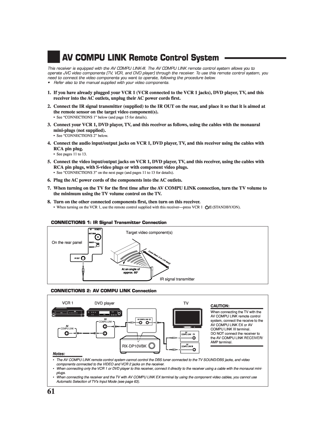
CONNECTIONS 1: IR Signal Transmitter Connection
AV COMPU LINK Remote Control System
CONNECTIONS 2: AV COMPU LINK Connection
CONNECTIONS 3: Video Cable Connection
One-TouchVideo Play
Automatic Power On/Off Standby
Automatic Power On
One-TouchDVD Play
Notes
Operating JVC’s Audio/Video Components
Operating Audio Components
Tuner
Sound control section Amplifier
CD player
CD player-changer
Turntable
CD recorder
VCR VCR connected to the VCR 1 jacks
Operating Video Components
DVD player
Changing the Preset Signal Codes
Operating Other Manufacturers’ Equipment
1.Set the TV operation mode selector to “TV.”
2.Press and hold TV/CATV/DBS STANDBY/ON
3.Enter manufacturer’s code using buttons 1-9,and
4. Enter manufacturer’s code using
1.Press and hold VCR STANDBY/ON 2.Press VCR
buttons 1–9,and
3. Enter manufacturer’s code using
1.Press and hold VCR STANDBY/ON 2.Press DVD
4. Release AUDIO ON
1. Press and hold AUDIO ON. STANDBY ON
Manufactures’ codes for DBS tuner
Storing the Remote Signals Manually
1. Set the LEARN/TRANSMIT
MAIN ROOM/SUB ROOM
selector to “LEARN.”
•Repeat steps 3 to 5 to store more signals in a
control
different remote mode source
Notes
3. Press the desired button
To use the stored signals
To erase the stored signals
1. Set the LEARN/TRANSMIT
Troubleshooting
PROBLEM
SOLUTION
POSSIBLE CAUSE
Continuous hissing or buzzing during FM reception
120 W per channel, min. RMS, driven into 8 Ω,
Specifications
Amplifier
Tuning Range
FM tuner IHF
AM tuner
General
Accessories
Authorized Service Centers
HOW TO LOCATE YOUR JVC SERVICE CENTER
Do not service the television yourself
LIMITED WARRANTY
WHAT YOU MUST DO FOR WARRANTY SERVICE
WHAT IS NOT COVERED
AUDIO-2
0701NHMMDWJEIN
VICTOR COMPANY OF JAPAN, LIMITED