Does the | No | |||
of the top of the main duct? | ||||
| ||||
|
|
|
| |
|
|
|
| |
Yes
Check the Damper itself
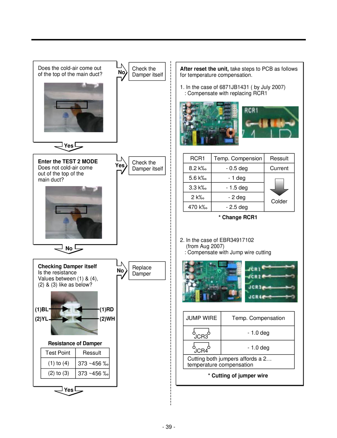
After reset the unit, take steps to PCB as follows for temperature compensation.
1.In the case of 6871JB1431 ( by July 2007)
:Compensate with replacing RCR1
Enter the TEST 2 MODE Does not
No
Checking Damper itself Is the resistance Values between (1) & (4),
(2) & (3) like as below?
(1)BL
(2)YL
Yes
No
(1)RD
(2)WH
Check the Damper itself
Replace
Damper
RCR1 | Temp. Compension | Ressult | |
8.2 k‰ | - 0.5 deg | Current | |
5.6 k‰ | - 1 deg |
| |
3.3 k‰ | - 1.5 deg |
| |
2 k‰ | - 2 deg | Colder | |
470 k‰ | - 2.5 deg | ||
| |||
| * Change RCR1 |
|
2.In the case of EBR34917102 (from Aug 2007)
:Compensate with Jump wire cutting
JUMP WIRE | Temp. Compensation |
JCR3 | - 1.0 deg |
|
Resistance of Damper
Test Point | Ressult |
(1)to (4) 373 ~456 ‰
(2)to (3) 373 ~456 ‰
Yes
JCR4 | - 1.0 deg |
|
Cutting both jumpers affords a 2… temperature compensation
* Cutting of jumper wire
- 39 -