Installation
![]()
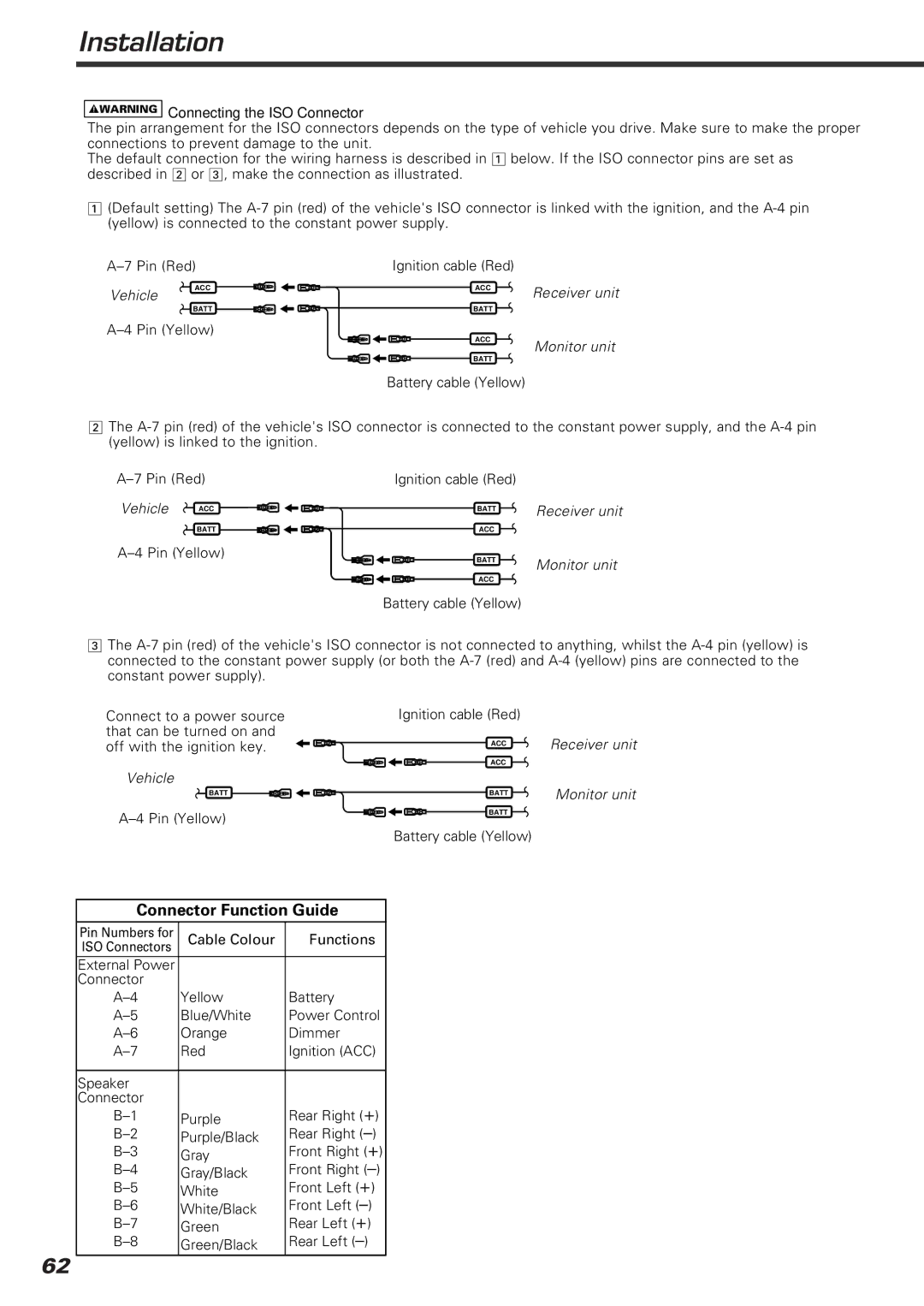
![]() Connecting the ISO Connector
Connecting the ISO Connector
The pin arrangement for the ISO connectors depends on the type of vehicle you drive. Make sure to make the proper connections to prevent damage to the unit.
The default connection for the wiring harness is described in 1 below. If the ISO connector pins are set as described in 2 or 3, make the connection as illustrated.
1(Default setting) The
Ignition cable (Red) |
| ||
Vehicle | ACC | ACC | Receiver unit |
|
| ||
| BATT | BATT |
|
ACC
Monitor unit
BATT
Battery cable (Yellow)
2The
Ignition cable (Red) |
| ||
Vehicle | ACC | BATT | Receiver unit |
|
| ||
| BATT | ACC |
|
| |
BATT | Monitor unit |
| |
ACC |
|
Battery cable (Yellow) |
|
3The
Connect to a power source that can be turned on and off with the ignition key.
Ignition cable (Red)
ACC | Receiver unit |
ACC |
|
Vehicle
BATT | BATT | Monitor unit |
BATT
Battery cable (Yellow)
Connector Function Guide
Pin Numbers for | Cable Colour | Functions |
ISO Connectors |
|
|
External Power |
|
|
Connector |
|
|
Yellow | Battery | |
Blue/White | Power Control | |
Orange | Dimmer | |
Red | Ignition (ACC) | |
|
|
|
Speaker |
|
|
Connector |
| Rear Right (+) |
Purple | ||
Purple/Black | Rear Right | |
Gray | Front Right (+) | |
Gray/Black | Front Right | |
White | Front Left (+) | |
White/Black | Front Left | |
Green | Rear Left (+) | |
Green/Black | Rear Left |
62