Installation
Connection
2WARNING
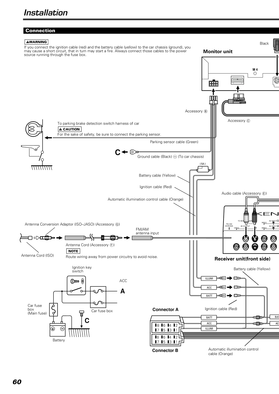
If you connect the ignition cable (red) and the battery cable (yellow) to the car chassis (ground), you may cause a short circuit, that in turn may start a fire. Always connect those cables to the power source running through the fuse box.
Black
Monitor unit
M 4
Accessory B
Accessory C
To parking brake detection switch harness of car
2CAUTION
For the sake of safety, be sure to connect the parking sensor.
Parking sensor cable (Green)
C![]()
Ground cable (Black) - (To car chassis)
( 5A )
Battery cable (Yellow)
Ignition cable (Red)
Audio cable (Accessory E)
Automatic illumination control cable (Orange)
Antenna Conversion Adaptor
FM/AM antenna input
TO
FM /AM
ANTENNA AV VIDEO
L |
UNIT
|
|
|
|
|
|
| AV INPUT 1 |
R | VIDEO | L | |
|
|
| AV INPUT 2 |
| VIDEO | L | |
|
|
|
|
Antenna Cord (Accessory F)
NOTE
Antenna Cord (ISO)
Car fuse box (Main fuse)
Route wiring away from power circuitry to avoid noise.
Ignition key switch
ACC
A
Car fuse box | Connector A |
|
Receiver unit(front side)
Battery cable (Yellow)
ILLUMI
ACC
BATT
Ignition cable (Red)
+
Battery
C
8 | 6 | 4 | 2 |
7 | 5 | 3 | 1 |
8 | 6 | 4 | 2 |
7 | 5 | 3 | 1 |
Connector B
BATT | BAT |
ACC | AC |
ILLUMI |
|
Automatic illumination control cable (Orange)
60