Kramer Electronics user manual Connecting the VP-725NA via the ETHERNET port, to PC

Models: VP-725NA

1 73
Download 73 pages 213 b
Page 23
Image 23
to PC

Hardware flow control is not required for this unit. In the rare case where a controller requires hardware flow control, short pin 1 to 7 and 8, and pin 4 to 6 on the controller side.

Method B (Figure 5)—Connect the RS-232 9-pin D-sub port on the unit via a straight (flat) cable to the null-modem adapter, and connect the null-modem adapter to the RS-232 9-pin D-sub port on the PC. The straight cable usually contains all nine wires for a full connection of the D-sub connector. Because the null-modem adapter (which already includes the flow control jumpering described in Method A above) only requires pins 2, 3 and 5 to be connected, you are free to decide whether to connect only these 3 pins or all 9 pins.

9

5

4

8

3

7

2

6

1


Null-Modem

Adapter

to PC

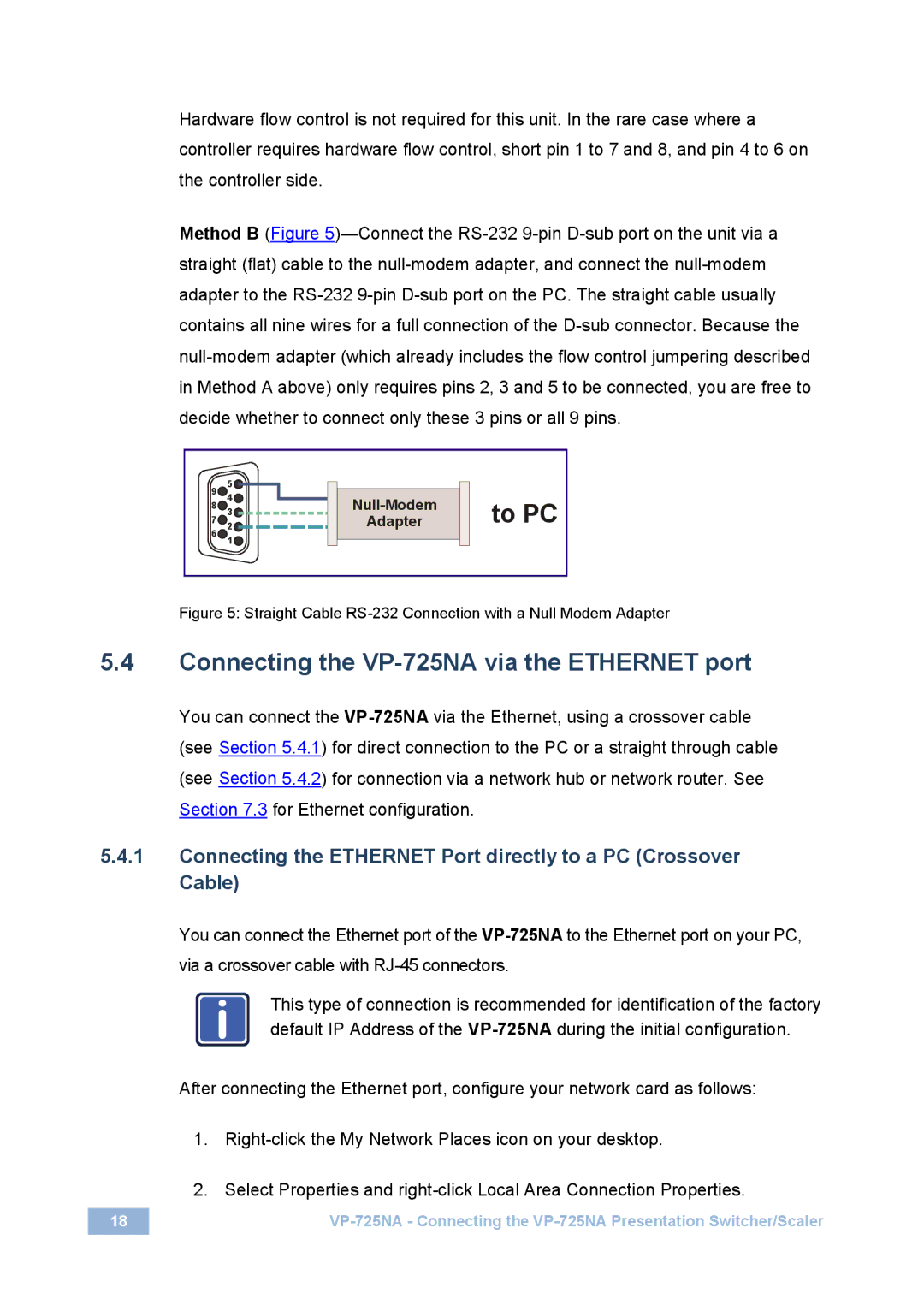
Figure 5: Straight Cable RS-232 Connection with a Null Modem Adapter

5.4Connecting the VP-725NA via the ETHERNET port

You can connect the VP-725NAvia the Ethernet, using a crossover cable (see Section 5.4.1) for direct connection to the PC or a straight through cable

(see Section 5.4.2) for connection via a network hub or network router. See Section 7.3 for Ethernet configuration.

5.4.1Connecting the ETHERNET Port directly to a PC (Crossover Cable)

You can connect the Ethernet port of the VP-725NAto the Ethernet port on your PC, via a crossover cable with RJ-45 connectors.

iThis type of connection is recommended for identification of the factory default IP Address of the VP-725NAduring the initial configuration.

After connecting the Ethernet port, configure your network card as follows:

1.Right-click the My Network Places icon on your desktop.

2.Select Properties and right-click Local Area Connection Properties.

18

VP-725NA - Connecting the VP-725NA Presentation Switcher/Scaler

Page 23
Image 23
Kramer Electronics user manual Connecting the VP-725NA via the ETHERNET port, to PC