3.Disconnect the heat sink and fan assembly cable from the microprocessor fan connector on the system board. See “Locating parts on the system board” on page 12.
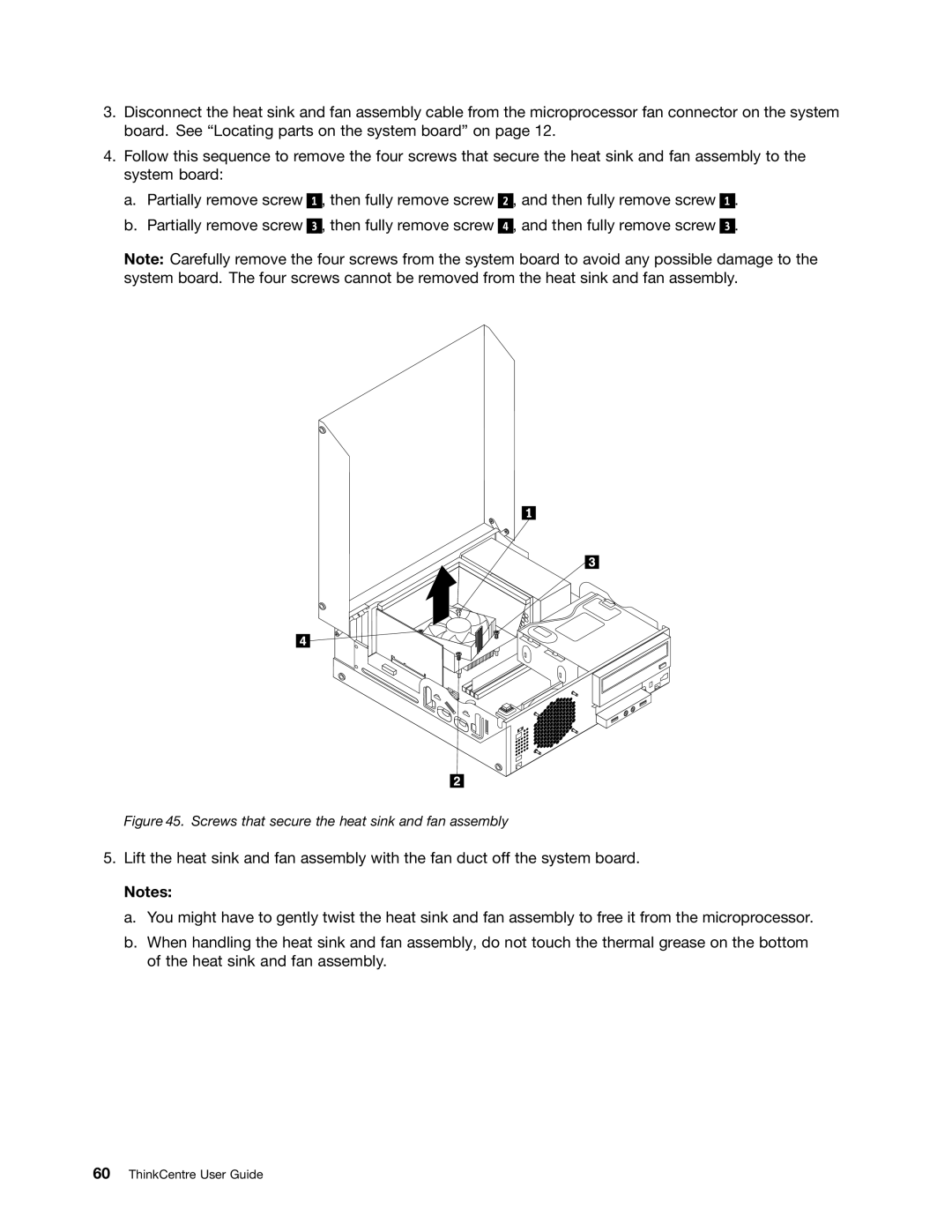
4.Follow this sequence to remove the four screws that secure the heat sink and fan assembly to the system board:
a.Partially remove screw
b.Partially remove screw
1 , then fully remove screw
3 , then fully remove screw
2 , and then fully remove screw
4 , and then fully remove screw
1.
3.
Note: Carefully remove the four screws from the system board to avoid any possible damage to the system board. The four screws cannot be removed from the heat sink and fan assembly.
Figure 45. Screws that secure the heat sink and fan assembly
5.Lift the heat sink and fan assembly with the fan duct off the system board.
Notes:
a.You might have to gently twist the heat sink and fan assembly to free it from the microprocessor.
b.When handling the heat sink and fan assembly, do not touch the thermal grease on the bottom of the heat sink and fan assembly.