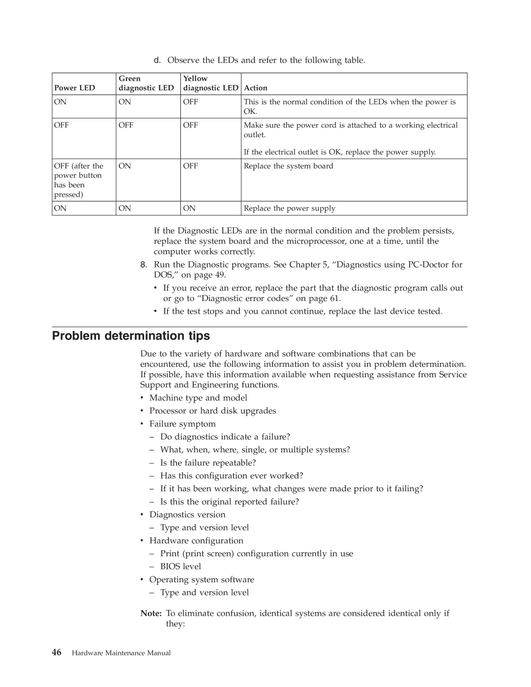
d.Observe the LEDs and refer to the following table.
| Green | Yellow |
|
Power LED | diagnostic LED | diagnostic LED | Action |
|
|
|
|
ON | ON | OFF | This is the normal condition of the LEDs when the power is |
|
|
| OK. |
|
|
|
|
OFF | OFF | OFF | Make sure the power cord is attached to a working electrical |
|
|
| outlet. |
|
|
| If the electrical outlet is OK, replace the power supply. |
|
|
|
|
OFF (after the | ON | OFF | Replace the system board |
power button |
|
|
|
has been |
|
|
|
pressed) |
|
|
|
|
|
|
|
ON | ON | ON | Replace the power supply |
|
|
|
|
If the Diagnostic LEDs are in the normal condition and the problem persists, replace the system board and the microprocessor, one at a time, until the computer works correctly.
8.Run the Diagnostic programs. See Chapter 5, “Diagnostics using
v If you receive an error, replace the part that the diagnostic program calls out or go to “Diagnostic error codes” on page 61.
vIf the test stops and you cannot continue, replace the last device tested.
Problem determination tips
Due to the variety of hardware and software combinations that can be encountered, use the following information to assist you in problem determination. If possible, have this information available when requesting assistance from Service Support and Engineering functions.
vMachine type and model
vProcessor or hard disk upgrades
vFailure symptom
–Do diagnostics indicate a failure?
–What, when, where, single, or multiple systems?
–Is the failure repeatable?
–Has this configuration ever worked?
–If it has been working, what changes were made prior to it failing?
–Is this the original reported failure?
vDiagnostics version
–Type and version level
vHardware configuration
–Print (print screen) configuration currently in use
–BIOS level
vOperating system software
–Type and version level
Note: To eliminate confusion, identical systems are considered identical only if they:
