|
|
|
| Alarm and Faults |
| |
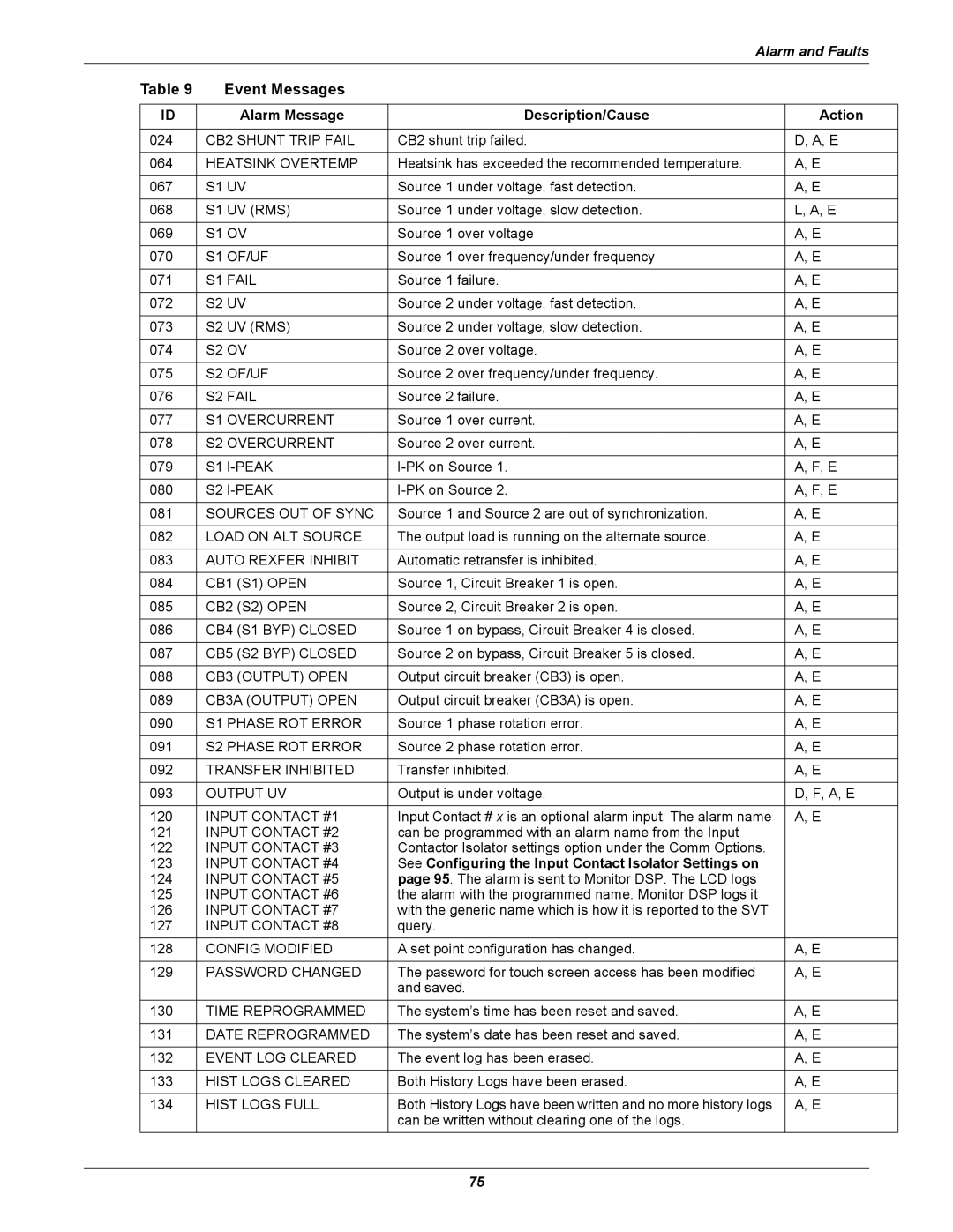
| Table 9 |
| Event Messages |
|
|
|
|
|
|
|
|
|
|
| ID |
| Alarm Message | Description/Cause | Action |
|
|
|
|
|
|
| |
| 024 | CB2 SHUNT TRIP FAIL | CB2 shunt trip failed. | D, A, E |
| |
|
|
|
|
|
| |
| 064 | HEATSINK OVERTEMP | Heatsink has exceeded the recommended temperature. | A, E |
| |
|
|
|
|
|
|
|
| 067 | S1 | UV | Source 1 under voltage, fast detection. | A, E |
|
|
|
|
|
|
|
|
| 068 | S1 | UV (RMS) | Source 1 under voltage, slow detection. | L, A, E |
|
|
|
|
|
|
|
|
| 069 | S1 | OV | Source 1 over voltage | A, E |
|
|
|
|
|
|
|
|
| 070 | S1 | OF/UF | Source 1 over frequency/under frequency | A, E |
|
|
|
|
|
|
|
|
| 071 | S1 | FAIL | Source 1 failure. | A, E |
|
|
|
|
|
|
|
|
| 072 | S2 | UV | Source 2 under voltage, fast detection. | A, E |
|
|
|
|
|
|
|
|
| 073 | S2 | UV (RMS) | Source 2 under voltage, slow detection. | A, E |
|
|
|
|
|
|
|
|
| 074 | S2 | OV | Source 2 over voltage. | A, E |
|
|
|
|
|
|
|
|
| 075 | S2 | OF/UF | Source 2 over frequency/under frequency. | A, E |
|
|
|
|
|
|
|
|
| 076 | S2 | FAIL | Source 2 failure. | A, E |
|
|
|
|
|
|
| |
| 077 | S1 OVERCURRENT | Source 1 over current. | A, E |
| |
|
|
|
|
|
| |
| 078 | S2 OVERCURRENT | Source 2 over current. | A, E |
| |
|
|
|
|
|
|
|
| 079 | S1 | A, F, E |
| ||
|
|
|
|
|
|
|
| 080 | S2 | A, F, E |
| ||
|
|
|
|
|
| |
| 081 | SOURCES OUT OF SYNC | Source 1 and Source 2 are out of synchronization. | A, E |
| |
|
|
|
|
|
| |
| 082 | LOAD ON ALT SOURCE | The output load is running on the alternate source. | A, E |
| |
|
|
|
|
|
| |
| 083 | AUTO REXFER INHIBIT | Automatic retransfer is inhibited. | A, E |
| |
|
|
|
|
|
| |
| 084 | CB1 (S1) OPEN | Source 1, Circuit Breaker 1 is open. | A, E |
| |
|
|
|
|
|
| |
| 085 | CB2 (S2) OPEN | Source 2, Circuit Breaker 2 is open. | A, E |
| |
|
|
|
|
|
| |
| 086 | CB4 (S1 BYP) CLOSED | Source 1 on bypass, Circuit Breaker 4 is closed. | A, E |
| |
|
|
|
|
|
| |
| 087 | CB5 (S2 BYP) CLOSED | Source 2 on bypass, Circuit Breaker 5 is closed. | A, E |
| |
|
|
|
|
|
| |
| 088 | CB3 (OUTPUT) OPEN | Output circuit breaker (CB3) is open. | A, E |
| |
|
|
|
|
|
| |
| 089 | CB3A (OUTPUT) OPEN | Output circuit breaker (CB3A) is open. | A, E |
| |
|
|
|
|
|
|
|
| 090 | S1 | PHASE ROT ERROR | Source 1 phase rotation error. | A, E |
|
|
|
|
|
|
|
|
| 091 | S2 | PHASE ROT ERROR | Source 2 phase rotation error. | A, E |
|
|
|
|
|
|
| |
| 092 | TRANSFER INHIBITED | Transfer inhibited. | A, E |
| |
|
|
|
|
|
| |
| 093 | OUTPUT UV | Output is under voltage. | D, F, A, E |
| |
|
|
|
|
|
| |
| 120 | INPUT CONTACT #1 | Input Contact # x is an optional alarm input. The alarm name | A, E |
| |
| 121 | INPUT CONTACT #2 | can be programmed with an alarm name from the Input |
|
| |
| 122 | INPUT CONTACT #3 | Contactor Isolator settings option under the Comm Options. |
|
| |
| 123 | INPUT CONTACT #4 | See Configuring the Input Contact Isolator Settings on |
|
| |
| 124 | INPUT CONTACT #5 | page 95. The alarm is sent to Monitor DSP. The LCD logs |
|
| |
| 125 | INPUT CONTACT #6 | the alarm with the programmed name. Monitor DSP logs it |
|
| |
| 126 | INPUT CONTACT #7 | with the generic name which is how it is reported to the SVT |
|
| |
| 127 | INPUT CONTACT #8 | query. |
|
| |
| 128 | CONFIG MODIFIED | A set point configuration has changed. | A, E |
| |
|
|
|
|
|
| |
| 129 | PASSWORD CHANGED | The password for touch screen access has been modified | A, E |
| |
|
|
|
| and saved. |
|
|
| 130 | TIME REPROGRAMMED | The system’s time has been reset and saved. | A, E |
| |
|
|
|
|
|
| |
| 131 | DATE REPROGRAMMED | The system’s date has been reset and saved. | A, E |
| |
|
|
|
|
|
| |
| 132 | EVENT LOG CLEARED | The event log has been erased. | A, E |
| |
|
|
|
|
|
| |
| 133 | HIST LOGS CLEARED | Both History Logs have been erased. | A, E |
| |
|
|
|
|
|
| |
| 134 | HIST LOGS FULL | Both History Logs have been written and no more history logs | A, E |
| |
|
|
|
| can be written without clearing one of the logs. |
|
|
75