STS2 Touch Screen Display
To configure the set points for each source:
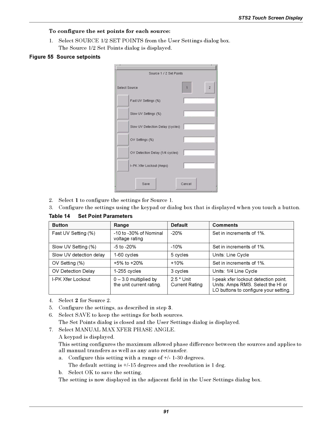
1.Select SOURCE 1/2 SET POINTS from the User Settings dialog box. The Source 1/2 Set Points dialog is displayed.
Figure 55 Source setpoints
2.Select 1 to configure the settings for Source 1.
3.Configure the settings using the keypad or dialog box that is displayed when you touch a button.
Table 14 Set Point Parameters
Button | Range | Default | Comments |
Fast UV Setting (%) | Set in increments of 1%. | ||
| voltage rating |
|
|
Slow UV Setting (%) | Set in increments of 1%. | ||
|
|
|
|
Slow UV detection delay | 5 cycles | Units: Line Cycle | |
|
|
|
|
OV Setting (%) | +5% to +20% | +10% | Set in increments of 1%. |
|
|
|
|
OV Detection Delay | 3 cycles | Units: 1/4 Line Cycle | |
|
|
|
|
0 – 3.0 multiplied by | 2.5 * Unit | ||
| the unit current rating. | Current Rating | Units: Amps RMS. Select the HI or |
|
|
| LO buttons to configure your setting. |
4.Select 2 for Source 2.
5.Configure the settings, as described in step 3.
6.Select SAVE to keep the settings for both sources.
The Set Points dialog is closed and the User Settings dialog is displayed.
7.Select MANUAL MAX XFER PHASE ANGLE. A keypad is displayed.
This setting configures the maximum allowed phase difference between the sources and applies to all manual transfers as well as any auto retransfer.
a.Configure this setting with a range of +/-
The default setting is
b.Select OK to save the setting.
The setting is now displayed in the adjacent field in the User Settings dialog box.
91