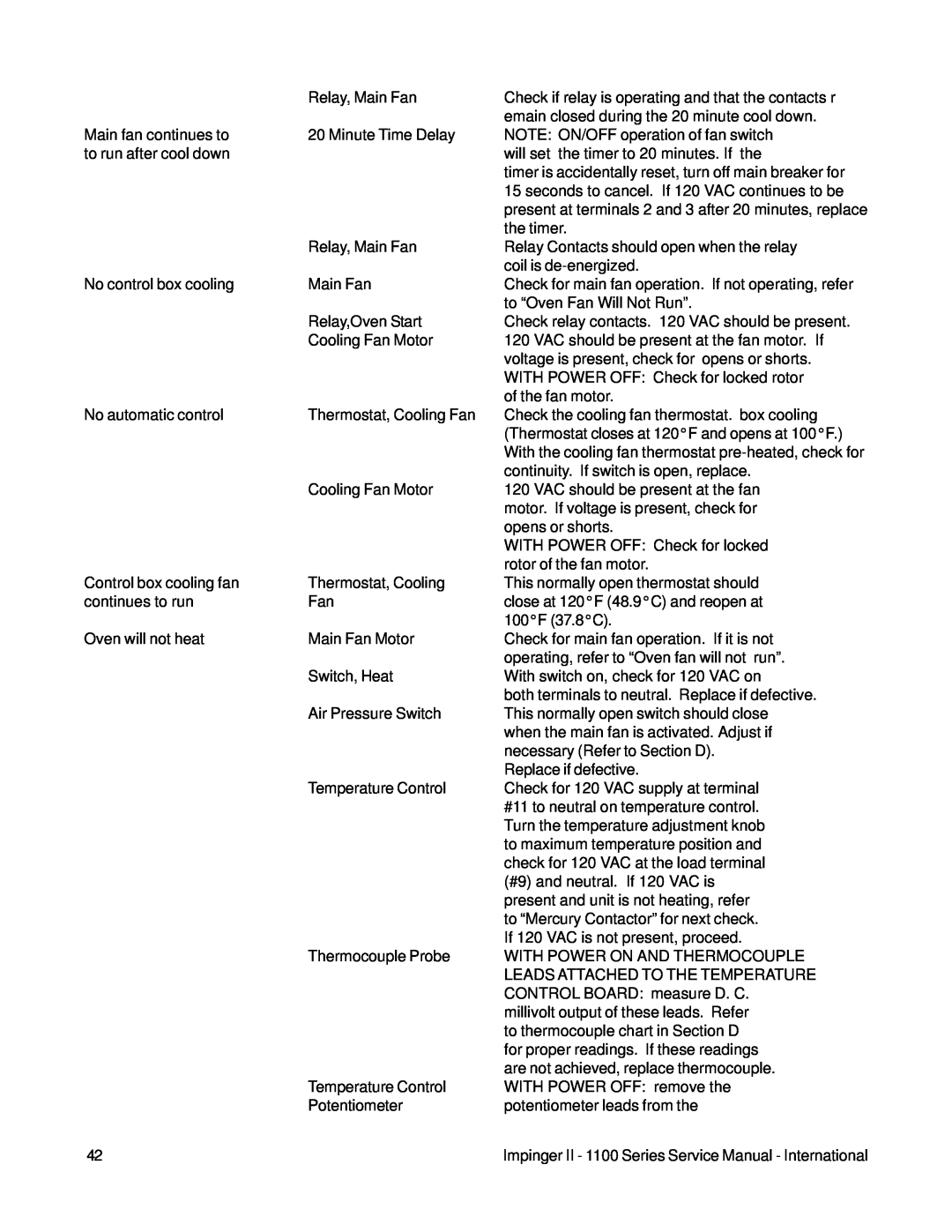
| Relay, Main Fan | Check if relay is operating and that the contacts r |
|
| emain closed during the 20 minute cool down. |
Main fan continues to | 20 Minute Time Delay | NOTE: ON/OFF operation of fan switch |
to run after cool down |
| will set the timer to 20 minutes. If the |
|
| timer is accidentally reset, turn off main breaker for |
|
| 15 seconds to cancel. If 120 VAC continues to be |
|
| present at terminals 2 and 3 after 20 minutes, replace |
|
| the timer. |
| Relay, Main Fan | Relay Contacts should open when the relay |
|
| coil is |
No control box cooling | Main Fan | Check for main fan operation. If not operating, refer |
|
| to “Oven Fan Will Not Run”. |
| Relay,Oven Start | Check relay contacts. 120 VAC should be present. |
| Cooling Fan Motor | 120 VAC should be present at the fan motor. If |
|
| voltage is present, check for opens or shorts. |
|
| WITH POWER OFF: Check for locked rotor |
|
| of the fan motor. |
No automatic control | Thermostat, Cooling Fan | Check the cooling fan thermostat. box cooling |
|
| (Thermostat closes at 120°F and opens at 100°F.) |
|
| With the cooling fan thermostat |
|
| continuity. If switch is open, replace. |
| Cooling Fan Motor | 120 VAC should be present at the fan |
|
| motor. If voltage is present, check for |
|
| opens or shorts. |
|
| WITH POWER OFF: Check for locked |
|
| rotor of the fan motor. |
Control box cooling fan | Thermostat, Cooling | This normally open thermostat should |
continues to run | Fan | close at 120°F (48.9°C) and reopen at |
|
| 100°F (37.8°C). |
Oven will not heat | Main Fan Motor | Check for main fan operation. If it is not |
|
| operating, refer to “Oven fan will not run”. |
| Switch, Heat | With switch on, check for 120 VAC on |
|
| both terminals to neutral. Replace if defective. |
| Air Pressure Switch | This normally open switch should close |
|
| when the main fan is activated. Adjust if |
|
| necessary (Refer to Section D). |
|
| Replace if defective. |
| Temperature Control | Check for 120 VAC supply at terminal |
|
| #11 to neutral on temperature control. |
|
| Turn the temperature adjustment knob |
|
| to maximum temperature position and |
|
| check for 120 VAC at the load terminal |
|
| (#9) and neutral. If 120 VAC is |
|
| present and unit is not heating, refer |
|
| to “Mercury Contactor” for next check. |
|
| If 120 VAC is not present, proceed. |
| Thermocouple Probe | WITH POWER ON AND THERMOCOUPLE |
|
| LEADS ATTACHED TO THE TEMPERATURE |
|
| CONTROL BOARD: measure D. C. |
|
| millivolt output of these leads. Refer |
|
| to thermocouple chart in Section D |
|
| for proper readings. If these readings |
|
| are not achieved, replace thermocouple. |
| Temperature Control | WITH POWER OFF: remove the |
| Potentiometer | potentiometer leads from the |
42 |
| Impinger II - 1100 Series Service Manual - International |
Page 42
Image 42