D C MOTOR CONTROL BOARD
|
|
|
|
|
| L 1 |
| A+ |
|
|
|
|
|
|
|
| ||||||
|
|
|
|
|
|
|
|
|
|
|
|
|
|
|
|
|
|
|
|
|
|
|
|
|
|
|
|
|
|
|
|
|
|
|
|
|
|
|
|
|
|
|
|
|
|
|
| 4 A. FUSE |
|
| 1 A. FUSE |
|
|
| . |
|
|
| ||||||||||
|
|
|
|
|
|
|
| RESISTOR |
| |||||||||||||
|
|
|
|
|
|
|
|
|
|
|
|
|
|
|
|
|
|
|
| |||
|
|
|
|
|
|
|
| L 2 |
|
|
|
|
|
|
|
|
|
|
|
|
| |
|
|
|
|
|
|
|
|
|
|
|
|
|
|
|
|
|
|
|
|
| ||
|
|
|
|
|
|
|
|
|
|
|
|
|
|
| A - |
|
| |||||
|
|
|
| P 2 |
|
|
|
|
|
|
|
|
|
|
|
|
| |||||
|
| P 3 |
|
| P 1 |
|
|
|
|
|
|
|
|
|
|
|
|
| ||||
|
|
|
|
|
|
|
|
|
|
|
|
|
|
|
|
| ||||||
|
|
|
|
|
|
|
|
|
|
|
|
|
|
|
|
|
|
|
|
|
|
|
|
|
|
|
|
|
|
|
|
|
|
|
|
|
|
|
|
|
|
|
|
|
|
|
|
|
|
|
|
|
|
|
|
|
|
|
|
|
|
|
|
|
|
|
|
|
|
|
|
|
|
|
|
|
|
|
|
|
|
|
|
|
|
|
|
|
|
|
|
MAX |
|
| MIN | IR CL TACH T 1 | T 2 | |||||||||||||||||
BOARD P/N 369155
STYLE 1
| L 1 | A+ |
|
|
4 A. FUSE | 1 A. FUSE | RESISTOR | ||
|
|
| ||
| L 2 |
|
|
|
|
| A - |
|
|
| P 2 |
|
|
|
P 3 | P 1 |
|
|
|
MAX | MIN |
| T 1 | T 2 |
| BOARD P/N 369155 |
|
| |
STYLE 2
|
| L 1 |
|
| L 2 |
|
|
| A - | A + | |||||||
|
|
|
|
|
|
|
|
|
|
|
|
|
|
|
|
|
|
|
|
|
|
|
|
|
|
|
|
|
|
|
|
| |||
|
|
|
|
|
|
|
|
|
|
|
|
| RESISTOR |
| |||
|
|
|
|
|
|
|
|
|
|
|
|
|
|
| |||
|
|
|
|
|
|
|
|
|
|
|
|
| CAPACITOR | ||||
|
|
|
|
|
|
| MIN |
| MAX |
|
| ||||||
| S 3 |
|
| S 1 |
|
|
|
|
| T 1 | T 2 | ||||||
|
|
|
| S 2 |
|
|
|
|
|
|
|
|
|
|
|
| |
|
|
|
|
|
|
|
|
|
|
|
|
|
| ||||
|
|
|
|
|
|
|
|
|
|
|
|
|
|
|
|
|
|
BOARD P/N 369155
STYLE 3
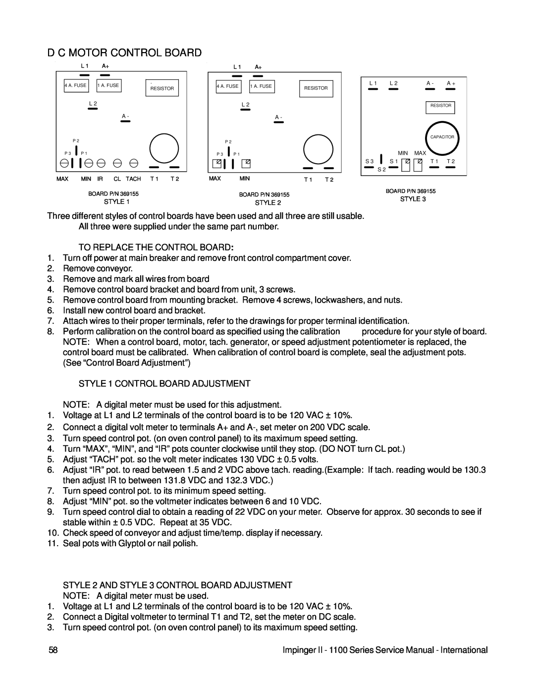
Three different styles of control boards have been used and all three are still usable.
All three were supplied under the same part number.
TO REPLACE THE CONTROL BOARD:
1.Turn off power at main breaker and remove front control compartment cover.
2.Remove conveyor.
3.Remove and mark all wires from board
4.Remove control board bracket and board from unit, 3 screws.
5.Remove control board from mounting bracket. Remove 4 screws, lockwashers, and nuts.
6.Install new control board and bracket.
7.Attach wires to their proper terminals, refer to the drawings for proper terminal identification.
8. Perform calibration on the control board as specified using the calibration procedure for your style of board. NOTE: When a control board, motor, tach. generator, or speed adjustment potentiometer is replaced, the control board must be calibrated. When calibration of control board is complete, seal the adjustment pots. (See “Control Board Adjustment”)
STYLE 1 CONTROL BOARD ADJUSTMENT
NOTE: A digital meter must be used for this adjustment.
1.Voltage at L1 and L2 terminals of the control board is to be 120 VAC ± 10%.
2.Connect a digital volt meter to terminals A+ and
3.Turn speed control pot. (on oven control panel) to its maximum speed setting.
4.Turn “MAX”, “MIN”, and “IR” pots counter clockwise until they stop. (DO NOT turn CL pot.)
5.Adjust “TACH” pot. so the volt meter indicates 130 VDC ± 0.5 volts.
6.Adjust “IR” pot. to read between 1.5 and 2 VDC above tach. reading.(Example: If tach. reading would be 130.3 then adjust IR to between 131.8 VDC and 132.3 VDC.)
7.Turn speed control pot. to its minimum speed setting.
8.Adjust “MIN” pot. so the voltmeter indicates between 6 and 10 VDC.
9.Turn speed control dial to obtain a reading of 22 VDC on your meter. Observe for approx. 30 seconds to see if stable within ± 0.5 VDC. Repeat at 35 VDC.
10.Check speed of conveyor and adjust time/temp. display if necessary.
11.Seal pots with Glyptol or nail polish.
STYLE 2 AND STYLE 3 CONTROL BOARD ADJUSTMENT
NOTE: A digital meter must be used.
1.Voltage at L1 and L2 terminals of the control board is to be 120 VAC ± 10%.
2.Connect a Digital voltmeter to terminal T1 and T2, set the meter on DC scale.
3.Turn speed control pot. (on oven control panel) to its maximum speed setting.
58 | Impinger II - 1100 Series Service Manual - International |