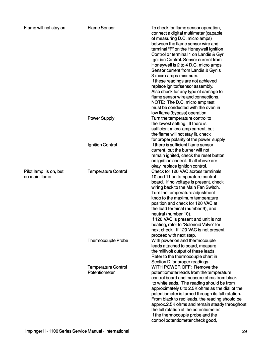
Flame will not stay on | Flame Sensor |
Power Supply
Ignition Control
Pilot lamp is on, but | Temperature Control |
no main flame |
|
Thermocouple Probe
Temperature Control
Potentiometer
Impinger II - 1100 Series Service Manual - International
To check for flame sensor operation, connect a digital multimeter (capable of measuring D.C. micro amps) between the flame sensor wire and terminal “F” on the Honeywell Ignition Control or terminal 1 on Landis & Gyr Ignition Control. Sensor current from Honeywell is 2 to 4 D.C. micro amps. Sensor current from Landis & Gyr is 3 micro amps minimum.
If these readings are not achieved replace ignitor/sensor assembly. Also check for any type of damage to flame sensor wire and connections. NOTE: The D.C. micro amp test must be conducted with the oven in low flame (bypass) operation.
Turn the temperature control to the lowest setting. If there is sufficient
for proper polarity of the power supply If there is sufficient flame sensor current, but the burner will not remain ignited, check the reset button on ignition control. If all above are okay, replace ignition control.
Check for 120 VAC across terminals 10 and 11 on temperature control board. If no voltage is present, check wiring back to the Main Fan Switch. Turn the temperature adjustment knob to the maximum temperature position and check for 120 VAC at the load terminal (number 9), and neutral (number 10).
If 120 VAC is present and unit is not heating, refer to “Solenoid Valve” for next check. If 120 VAC is not present, proceed with next step.
With power on and thermocouple leads attached to board, measure the millivolt output of these leads. Refer to the thermocouple chart in Section D for proper readings.
WITH POWER OFF: Remove the potentiometer leads from the temperature control board and measure ohms from black to whiteleads. The reading should be from approximately 0 to 2.5K ohms as the dial of the potentiometer is turned through its full rotation. From black to red leads, the reading should be approx.2.5K ohms and remain steady throughout the full rotation of the potentiometer.
If the thermocouple probe and the control potentiometer check good,
29