REMOVAL, INSTALLATION, AND ADJUSTMENT
IMPINGER II CONVEYOR OVEN
MOTOR, MAIN FAN
1.Shut off power at main breaker.
2.Disconnect motor wiring of main fan motor, note wire colors for reassembly, and remove entire oven back from the oven. Refer to “main fan” (See Below) for removal information.
3.Remove the main fan.
4.Remove 4 screws from the motor support assembly.
5.Remove the motor mounting clamp and pull the motor away from the oven back assembly.
6.Remove motor mounting fixture.
7.Install the motor in reverse order insuring that the motor shaft is centered in the
8.Shaft tube of the oven back.
CAPACITOR, MOTOR Model
Capacitor is located under motor cover in rear of unit and held in place by a plastic wire tie.
1Discharge capacitor, remove and replace. FOR ALL OTHER 1100 MODELS
Capacitor is located under rear control box cover and held in place by a plastic wire tie.
MAIN FAN
1.Shut off power at main breaker.
2.Remove motor cover from back of oven.
3.Disconnect and mark motor wiring of main fan motor and remove entire oven back from oven.
NOTE: Turning the oven back bolts back and forward while applying a spray lubricant or penetrating oil will help minimize breakage.
4.Loosen and remove set screw in hub of fan.
5.Remove fan. The motor shaft has a flat making removal of fan fairly easy. If trouble is encountered, apply a
spray lubricant or penetrating oil in set screw hole and on motor shaft. NOTE: This fan is balanced by the manufacturer and must be handled carefully. Suggested storage is by suspending the fan through the shaft hole.
6.Reinstall fan with the tips of the fan blade closest to the oven back.
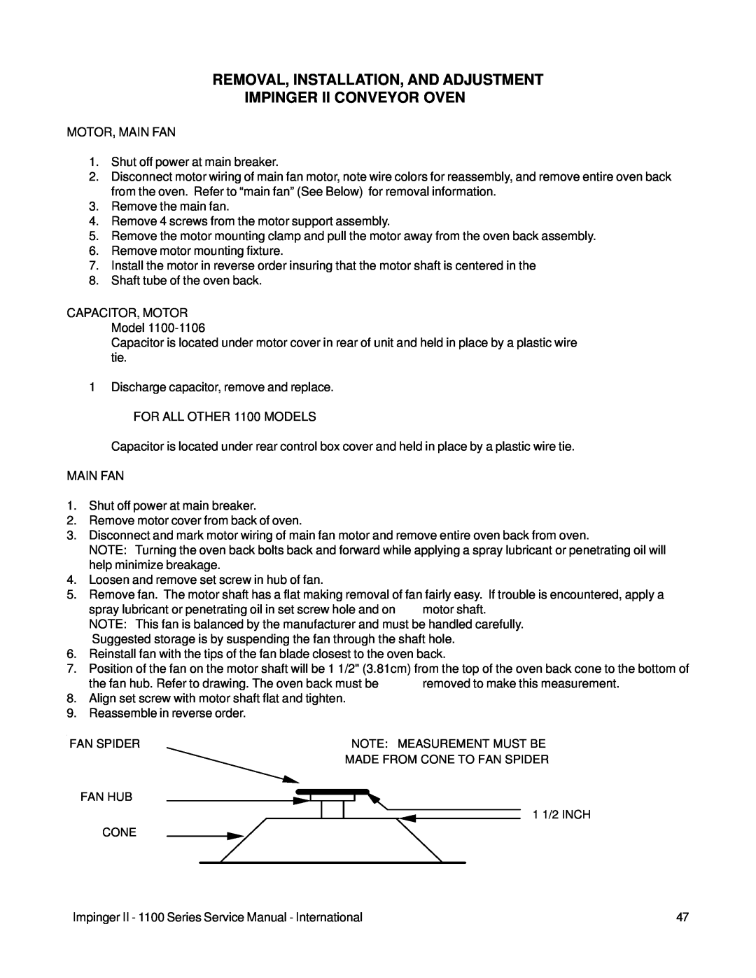
7.Position of the fan on the motor shaft will be 1 1/2" (3.81cm) from the top of the oven back cone to the bottom of
| the fan hub. Refer to drawing. The oven back must be | removed to make this measurement. |
8. | Align set screw with motor shaft flat and tighten. |
|
9. | Reassemble in reverse order. |
|
FAN SPIDER
FAN HUB
CONE
NOTE: MEASUREMENT MUST BE MADE FROM CONE TO FAN SPIDER
1 1/2 INCH
Impinger II - 1100 Series Service Manual - International | 47 |