SERVICE MANUAL
IMPINGER CONVEYOR OVENS
MODEL 1100 SERIES
INTERNATIONAL
TABLE OF CONTENTS
SEQUENCE OF OPERATIONS 1104 thru
the display into a temperature reading
SEQUENCE OF OPERATION 1134 - 1135 - 1136 -
S/N 2011383 and above
SEQUENCE OF OPERATIONS
2011383 and above
SEQUENCE OF OPERATIONS 1152 thru
intervals to maintain desired temperature
temperature reading
by the display into a temperature reading
SCHEMATIC
SCHEMATIC
SCHEMATIC 1134, 1135, 1150, S/N 2011383 AND BELOW
SCHEMATIC 1134, 1135 S/N 2011383 AND ABOVE
SCHEMATIC 1150 S/N 2011383 AND ABOVE
SCHEMATIC 1136, S/N 2011383 AND BELOW
SCHEMATIC 1136, S/N 2011383 AND ABOVE
SCHEMATIC 1151 S/N 2011383 AND BELOW
SCHEMATIC 1151 S/N 2011383 AND ABOVE
SCHEMATIC1152 THRU 1158 S/N 2011383 AND BELOW
SCHEMATIC1152 THRU 1158 S/N 2011383 AND ABOVE
SCHEMATIC1152 AND 1153 S/N 2011821 AND ABOVE
SCHEMATIC 1154 THRU 1158 S/N 2011821 AND ABOVE
TROUBLE SHOOTING GUIDE GAS OVENS
MODELS 1152 - 1153 - 1154 - 1155 - 1156
No main fan cool down
Burner Switch
switch. If switch is closed and voltage
present on one side only, replace switch
Gas Pressure Switch
Check for proper line voltage to
Power Supply Ignition Control
Flame will not stay on
Flame Sensor
Pilot lamp is on, but
then the problem is usually with thetemperature
improper adjustment. Also check for worn
bearings. TheInstallation and Operations Manual
Power Supply
Check power supply at the DC
DC Gearmotor
surge in the incoming power lines. To eliminate
this condition remove power from the time/temp
switch for 15 seconds, or if display stays on
required. This should eliminate the problem. If
TROUBLE SHOOTING GUIDE ELECTRIC OVENS
Switch, Heat
Air Pressure Switch
This normally open switch should close when the
adjustment knob to maximum temperature position
as follows
MODEL
Main fan runs after
WITH POWER OFF: To check resistance of the
maintenance. Also, most of the problems
for proper readings. If these readings
are not achieved, replace thermocouple
Conveyor will not run
TROUBLESHOOTING GUIDE ELECTRIC OVEN
MODEL 1151 200 VAC THREE PHASE 60 HZ
Relay, Main Fan
Mercury Contactor Heater Elements
Conveyor will not run S/N 2011383 and above
REFER TO PAGE REFER TO PAGE REFER TO PAGE
REFER TO PAGE REFER TO PAGE 43
STEPPER MOTOR DRIVE Conveyor will not run
12 VAC Power Supply
yellow wires, thermo
red wire and 1 white wire
Thermocouple Probe Power Supply
experienced, such as a rolling of
REMOVAL, INSTALLATION, AND ADJUSTMENT
IMPINGER II CONVEYOR OVEN
RELAY, DPST 1.Shut off power at main breaker
This is part of the burner blower motor assembly
TO REMOVE THE BLOWER WHEEL FOR PERIODIC CLEANING
MOTOR, BURNER BLOWER
TO REMOVE BLOWER MOTOR
AIR PRESSURE SWITCH
Page
Page
1.Shut off power at the main breaker
SOLENOID VALVE 1.Shut off power at main breaker
5.Loosen pipe union in piping assembly
HEATING ELEMENTS 1.Shut off power at main breaker
IGNITION CONTROL 1.Shut off power at main breaker
ORIFICE, MAIN BURNER
2.Shut off gas at main line to the oven
4.Remove control compartment covers
5.Loosen 4 nuts holding manifold to burner cap
LAMP, PILOT BURNER LENS, PILOT LAMP
OPTICAL ENCODER ASSEMBLY
1.Remove gearmotor assembly see “GEARMOTOR” Above
7.To adjust optical encoder
TACH. GENERATOR 1.Turn off power at main breaker
D C MOTOR CONTROL BOARD
1.Turn off power and remove conveyor
4.Reverse wires fastened to terminals A+ and A
5.Reverse wires fastened to terminals T1 and T2
1.Turn off power 2.Remove conveyor
TRANSFORMER, TIME/TEMP. DISPLAY
MODEL 1100 SERIES OVENS
OHMS
SWITCH, DISPLAY, SET
OVEN TEMPERATURE
SWITCH, ON/OFF
TRANSFORMER, STEP DOWN/120 VAC
DIP SWITCHES FOR 50 SEC. TO 30 MIN. TIMES
maximum speed potrefer
HALL EFFECT SENSOR - REPLACEMENT
AIR PRESSURE SWITCH, BURNER OR OVEN CAVITY
BURNER ALARM - REPLACEMENT
4.Remove conveyor gear motor
8.Remove top control compartment brace
10.Assemble in reverse order
DESCRIPTION
GENERAL –1100SERIES
LETTER
GENERAL 1100 SERIES BLOW UP
1136,1150,1151,1160 Thru1163
Page
CONTROL COMPARTMENT - FRONT
MODELS 1152 THRU
LETTER
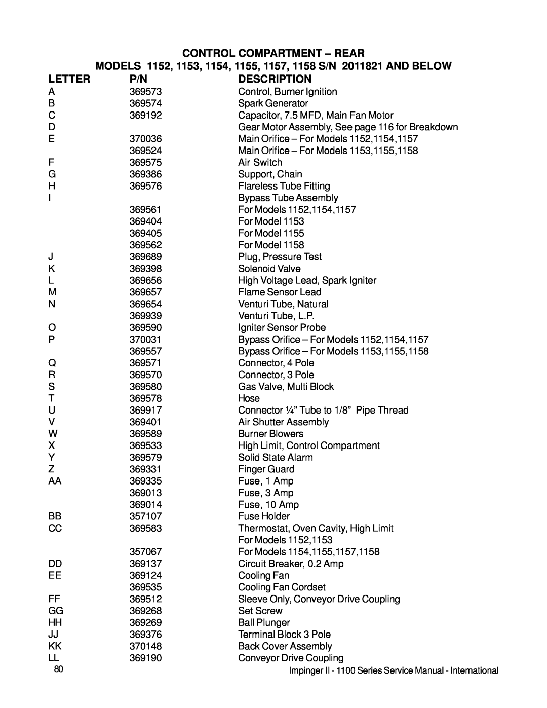
DESCRIPTION
CONTROL COMPARTMENT – FRONT 1152-1158BLOW UP
DESCRIPTION
CONTROL COMPARTMENT – REAR
LETTER
CONTROL COMPARTMENT - REAR BLOW UP MODELS
AND ABOVE
MODELS 1160-1163S/N 2011978 AND ABOVE
CONTROL COMPARTMENT – REAR BLOW UP
MODELS 1130-1136,1150,1151S/N 2011383 AND ABOVE
DESCRIPTION
CONTROL COMPARTMENT – REAR
LETTER
Page
CONTROL COMPARTMENT – REAR
MODELS 1152 THRU 1158 S/N 2011821 AND ABOVE
LETTER
DESCRIPTION
Page
OVEN BACK ASSEMBLY – 1100 SERIES
OVEN BACK ASSEMBLY – 1100 SERIES BLOW UP
GEARMOTOR ASSEMBLY – 1100 SERIES
GEARMOTOR ASSEMBLY – 1100 SERIES BLOW UP
CONVEYOR/DOOR – 1100 SERIES
CONVEYOR/DOOR – 1100 SERIES BLOW UP
This page intentionally left blank
This page intentionally left blank