Return to Section TOC
Return to Section TOC
Return to Section TOC
Return to Section TOC
Return to Master TOC
Return to Master TOC
Return to Master TOC
Return to Master TOC
TROUBLESHOOTING & REPAIR |
|
| |||||
TROUBLESHOOTING GUIDE |
| Observe Safety Guidelines | |||||
|
|
| detailed in the beginning of this manual. | ||||
|
|
|
|
|
|
| |
| PROBLEMS |
| POSSIBLE AREAS OF | RECOMMENDED |
|
| |
| (SYMPTOMS) |
| MISADJUSTMENT(S) | COURSE OF ACTION |
| ||
|
|
|
|
|
|
|
|
|
|
| FEEDING PROBLEMS |
|
|
|
|
|
|
|
|
|
| ||
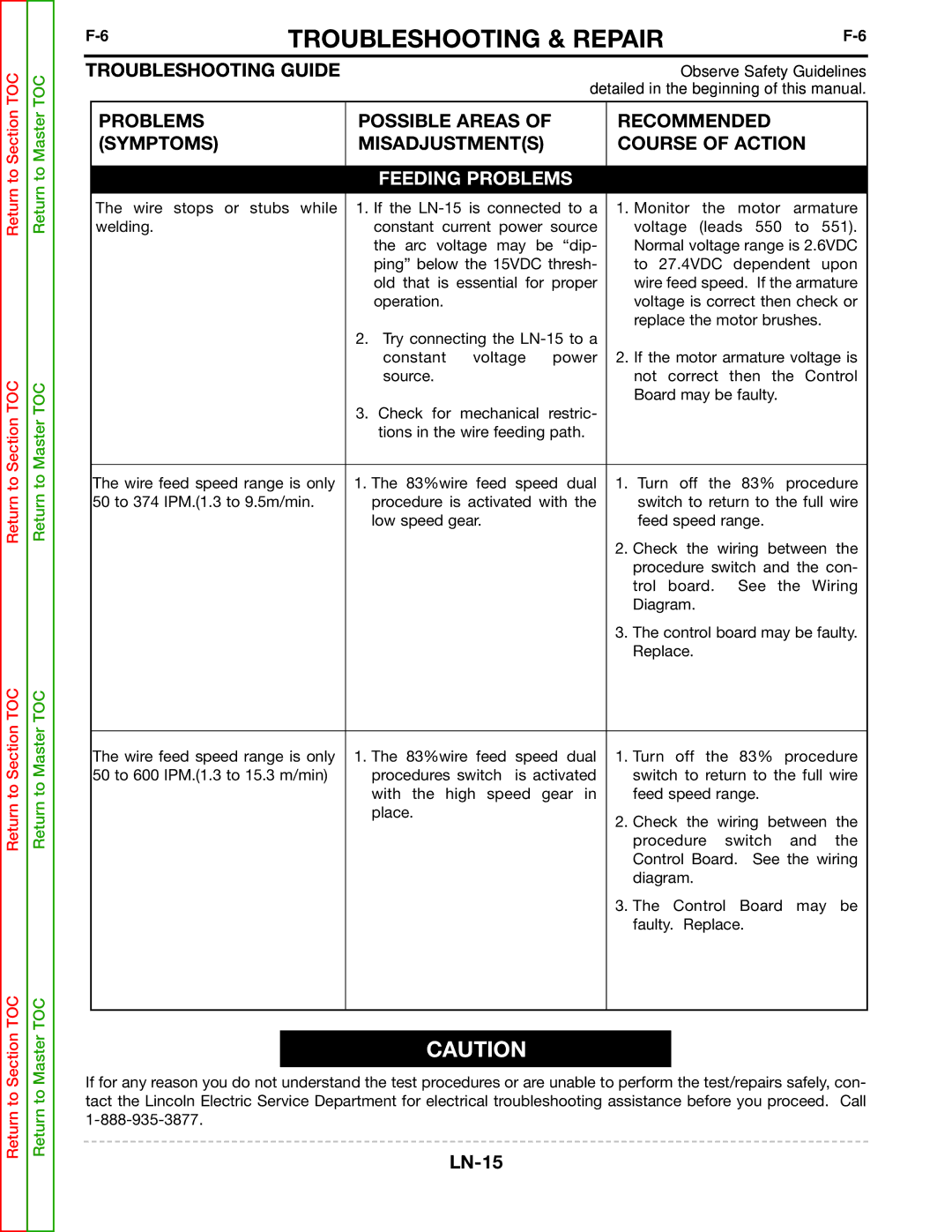
| The wire stops or stubs while | 1. If the | 1. Monitor the | motor | armature | ||
| welding. |
| constant current power source | voltage (leads 550 to 551). | |||
|
|
| the arc voltage may be “dip- | Normal voltage range is 2.6VDC | |||
|
|
| ping” below the 15VDC thresh- | to 27.4VDC | dependent upon | ||
|
|
| old that is essential for proper | wire feed speed. If the armature | |||
|
|
| operation. | voltage is correct then check or | |||
|
|
|
| replace the motor brushes. |
| ||
|
|
| 2. Try connecting the |
|
|
|
|
|
|
| constant voltage power | 2. If the motor armature voltage is | |||
|
|
| source. | not correct then the Control | |||
|
|
|
| Board may be faulty. |
|
| |
|
|
| 3. Check for mechanical restric- |
|
|
|
|
|
|
| tions in the wire feeding path. |
|
|
|
|
|
|
|
| ||||
| The wire feed speed range is only | 1. The 83%wire feed speed dual | 1. Turn off the 83% procedure | ||||
| 50 to 374 IPM.(1.3 to 9.5m/min. | procedure is activated with the | switch to return to the full wire | ||||
|
|
| low speed gear. | feed speed range. |
|
| |
|
|
|
| 2. Check the wiring between the | |||
|
|
|
| procedure switch and the con- | |||
|
|
|
| trol board. See the Wiring | |||
|
|
|
| Diagram. |
|
|
|
|
|
|
| 3. The control board may be faulty. | |||
|
|
|
| Replace. |
|
|
|
|
|
|
| ||||
| The wire feed speed range is only | 1. The 83%wire feed speed dual | 1. Turn off the 83% procedure | ||||
| 50 to 600 IPM.(1.3 to 15.3 m/min) | procedures switch is activated | switch to return to the full wire | ||||
|
|
| with the high speed gear in | feed speed range. |
|
| |
|
|
| place. | 2. Check the wiring between the | |||
|
|
|
| ||||
|
|
|
| procedure | switch | and | the |
|
|
|
| Control Board. See the wiring | |||
|
|
|
| diagram. |
|
|
|
|
|
|
| 3. The Control Board | may | be | |
|
|
|
| faulty. Replace. |
|
| |
|
|
|
|
|
|
|
|
CAUTION
If for any reason you do not understand the test procedures or are unable to perform the test/repairs safely, con- tact the Lincoln Electric Service Department for electrical troubleshooting assistance before you proceed. Call
